background image

Installation and Commissioning Guide - Classic 2 Split Ducted Outdoor Unit

Doc. No.0525-073  Ver. 8  210414

Installation and Commissioning Guide

Classic 2 Outdoor Units


46

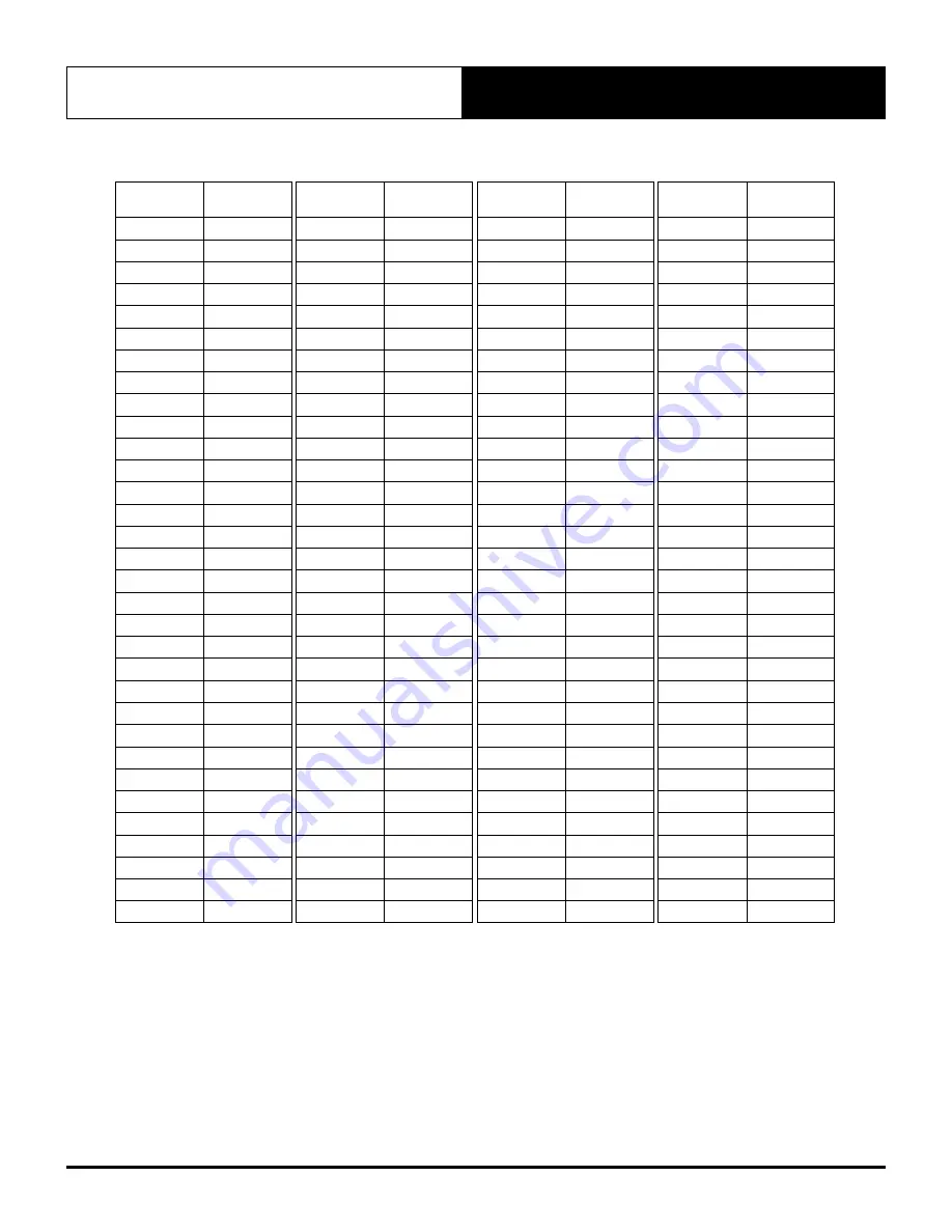
CHARGING TABLE

Temp


o

C

Pressure 

KPa

Temp


o

C

Pressure 

KPa

Temp


o

C

Pressure 

KPa

Temp


o

C

Pressure 

KPa

- 60

- 34.4

- 28

194.9

4

805.9

36

2090.7

- 59

- 30.7

- 27

206.9

5

834.1

37

2145.5

- 58

- 26.8

- 26

219.2

6

862.9

38

2201.3

- 57

- 22.8

- 25

231.9

7

892.6

39

2258.2

- 56

- 18.6

- 24

245.1

8

922.8

40

2316.1

- 55

- 14.2

- 23

258.7

9

953.8

41

2375.1

- 54

- 9.6

- 22

272.6

10

985.4

42

2435.1

- 53

- 4.8

- 21

286.9

11

1017.8

43

2496.2

- 52

0.8

- 20

301.7

12

1050.9

44

2558.5

- 51

5.3

- 19

316.9

13

1084.7

45

2621.8

- 50

10.7

- 18

332.6

14

1119.2

46

2686.2

- 49

16.3

- 17

348.7

15

1154.6

47

2751.8

- 48

22.2

- 16

365.2

16

1190.7

48

2818.5

- 47

28.2

- 15

382.3

17

1227.5

49

2886.4

- 46

34.0

- 14

399.7

18

1265.2

50

2955.5

- 45

40.9

- 13

417.7

19

1303.6

51

3025.7

- 44

47.8

- 12

436.2

20

1342.9

52

3097.2

- 43

54.8

- 11

455.1

21

1382.9

53

3169.9

- 42

62.1

- 10

474.6

22

1423.9

54

3243.7

- 41

69.6

- 9

494.6

23

1465.7

55

3318.9

- 40

77.4

- 8

515.1

24

1508.3

56

3395.2

- 39

85.5

- 7

536.2

25

1551.8

57

3472.9

- 38

93.9

- 6

557.8

26

1596.2

58

3551.8

- 37

102.5

- 5

579.9

27

1641.4

59

3631.9

- 36

111.5

- 4

602.6

28

1687.6

60

3713.5

- 35

120.8

- 3

625.9

29

1734.6

61

3796.3

- 34

130.4

- 2

649.8

30

1782.6

62

3880.5

- 33

140.3

- 1

674.3

31

1831.6

63

3965.9

- 32

150.5

0

699.4

32

1881.5

64

4052.8

- 31

161.1

1

724.9

33

1932.3

65

4140.9

- 30

171.9

2

751.3

34

1984.1

66

4230.6

- 29

183.3

3

778.3

35

2036.9

67

4321.5

Summary of Contents for Classic 2 CCA130S

Page 1: ...Classic Condenser Add On Cooling Only CRA100S CRA130S CRA130T CRA150S CRA150T CRA170S CRA170T CRA200T CRA230T CCA130S CCA150S CCA170S CCA170T CCA200T CCA230T IMPORTANT NOTE Please read this manual ca...

Page 2: ...17 10 Outdoor Unit Preparation 19 11 Field Pipe Connection 20 11 01 Piping and Brazing 20 11 02 Pressure Testing 24 11 03 Evacuation Procedure Triple Evacuation 24 12 Electrical Installation 25 13 Sp...

Page 3: ...73 Ver 8 210414 03 18 Indoor Fan Commissioning via Third Party Control 37 18 01 EVA100S EFA100S 37 18 02 EVA130S EFA130S 38 18 03 EVA150S EFA150S 39 18 04 EVA170S EFA170S 40 18 05 EVA200S EFA200S 41 1...

Page 4: ...ctronic control For optimum efficiency your air conditioning unit will deliver just the right amount of cooling or heating capacity you demand Even in extreme conditions the unit will still supply the...

Page 5: ...capacity that are among the best in the market the ActronAir air conditioning units provide the solution for the reduction of energy consumption CO2 emission high fuel dependency and high network gri...

Page 6: ...t be licensed to handle refrigerant gases Recover and Recycle Refrigerants Never release refrigerant to the atmosphere It is an offence in Australia to do so Always recover recycle and reuse refrigera...

Page 7: ...ial units up to 23kW split ducted Allow minimum recommended clearances for periodic maintenance and service access Allow sufficient space above the unit for the outdoor air discharge Condenser air inl...

Page 8: ...it Ducted Outdoor Unit Doc No 0525 073 Ver 8 210414 Installation and Commissioning Guide Classic 2 Outdoor Units 8 06 Components Overview HP CONTROL COMPRESSOR FANS CONTROL PANEL COIL ASSEMBLY DISCHAR...

Page 9: ...dd On Cooling for CCA models only START CAPACITOR RUN CAPACITOR SINGLE PHASE SOFT STARTER COMPRESSOR TERMINAL BLOCKS MAIN TERMINAL BLOCK FAN SPEED CAPACITORS CONTROL BOARD CONTROL CIRCUIT BREAKER FAN...

Page 10: ...210414 Installation and Commissioning Guide Classic 2 Outdoor Units 10 07 03 Three Phase Soft Starter Option 13 23 kW 3 PHASE SOFT STARTER FAN SPEED CAPACITORS CONTROL BOARD CONTROL CIRCUIT BREAKER 2...

Page 11: ...clearance free of any obstructions 5 Maximum External Static of Outdoor Fans is 5 Pa 6 STACKING OF UNITS Ensure that minimum airflow and clearances are met 7 Refer to pipe Connection Details on Specif...

Page 12: ...nsional drawing for mounting hole details 2 Service Access Areas and Spaces for Airflow Clearances given above are suggested minimum based on the condition that the spaces around the units are free fr...

Page 13: ...nsional drawing for mounting hole details 2 Service Access Areas and Spaces for Airflow Clearances given above are suggested minimum based on the condition that the spaces around the units are free fr...

Page 14: ...rawing for mounting hole details 2 Service Access Areas and Spaces for Airflow Clearances given above are suggested minimum based on the condition that the spaces around the units are free from any ob...

Page 15: ...mounting hole details 2 Service Access Areas and Spaces for Airflow Clearances given above are suggested minimum based on the condition that the spaces around the units are free from any obstructions...

Page 16: ...in mm unless specified Refer to corresponding unit dimensional drawing for mounting hole details 2 Service Access Areas and Spaces for Airflow Clearances given above are suggested minimum based on th...

Page 17: ...nds of slings into shackle Equipment Required For Crane Lifting 1 Shackle 2 x Nylon Slings Spreader bars Refer to catalogue for unit weight before selecting shackles and slings NOTE Refer to Unit Dime...

Page 18: ...ere personal injury or death Please check unit weight and weight distribution points as shown in the unit drawing dimensions section Procedure 1 To move the unit around with a forklift insert the fork...

Page 19: ...below 2 Remove Access Panel Remove Access Panel Electrical as illustrated below A Removal Order Pull Out 20mm Pull Down to remove Access Panel Electrical A B B Access Panel REMOVE ACCESS PANEL 3 Inst...

Page 20: ...to perform any work described in this guide All work must be carried out in accordance with Australia and New Zealand refrigerant handling code of practice Maximum allowable total equivalent field pi...

Page 21: ...Supply INDOOR UNIT Example of Total Equivalent Field Pipe Length Calculations CAUTION Above illustration shown as calculation examples only It is the responsibility of the Installer to design an effic...

Page 22: ...Included in maximum field pipe length 2 Cut Swaged End on the unit to fit field pipe TABLE 3 REFRIGERATION PIPING THREE PHASE Reverse Cycle Outdoor Indoor CRA130T EVA130S CRA150T EVA150S CRA170T EVA1...

Page 23: ...ssure in evaporator and remove caps 5 Fit copper tube into tail set nitro bottle and regulator up at condenser end of pipe work 6 Fit nitrogen line into liquid line with rubber bung to seal the connec...

Page 24: ...t be removed at all costs Oxygen air reacts with the compressor oil and can lead to faults such as compressor failure BRAZE JOINTS To Indoor Unit See Diagram Below N I T R O G E N NITROGEN HOSE 11 03...

Page 25: ...Supply and Power Requirements Procedure It is the installer s responsibility to provide power supply wiring to the mains supply terminal strip of the outdoor unit Make sure all wiring are in accordanc...

Page 26: ...the back of electrical box cover SUB MAIN TO UNIT INDOOR UNIT WALL CONTROL SUB MAINS ISOLATOR Field Supplied by Installer SUB MAINS CIRCUIT BREAKER INTER CONNECTING DATA CONTROL CABLE INDOOR TO OUTDOO...

Page 27: ...used for the Data Terminal in Outdoor Unit match the Data Terminal in Indoor unit Outdoor Unit Data Terminal Green Plug Terminal A White Wire Terminal B Black Wire Terminal G Shield Wire Indoor Unit...

Page 28: ...30T EVA230S EFA230S CCA230T EVA230S EFA230S 25 0 4 0 1 0 Suggested Minimum Cable Size should be used as a guide only refer to the latest edition of the AS NZS 3000 Australian New Zealand Wiring Rules...

Page 29: ...ONTROLLER 2 OPTIONAL NOTES Diagram shown above is a general representation only Refer to individual unit wiring diagram for complete wiring connection details Long runs beside Mains cables or TV anten...

Page 30: ...m shown below is a general representation only Refer to individual unit wiring diagram for complete wiring connection details Long runs beside Mains cables or TV antenna cables should be avoided where...

Page 31: ...TROL BOARD CUT OFF GR GR WH RJ45 WALL CONTROL WIRING POWER BROWN ORANGE 485 A BLUE 485 B BLUE WHITE GND BROWN WHITE ORANGE WHITE NOT USED GREEN GREEN WHITE 15 02 NEO Wall Control Wiring Connections 15...

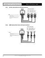
Page 32: ...1 PAIR 2 PAIR 2 PAIR 1 PAIR 1 PAIR 1 PAIR 2 PAIR 2 REMOTE SENSOR WIRING PAIR 1 BLUE BLUE WHITE PAIR 2 ORANGE ORANGE WHITE PAIR 3 GREEN GREEN WHITE PAIR 4 BROWN BROWN WHITE 15 04 AERSS Optional Duct Se...

Page 33: ...able Range Operating Mode DRM1 Compressor Off Mode Compressor ONLY will cycle Off remain Off for the entire Demand Response event All other functions will operate as normal i e Indoor Fan DRM2 Maximum...

Page 34: ...door unit Wall Controller ActronAir offers NEO LR7 1 and LC7 2 a wall controller that can control the available features and maximise the function and operation of the ActronAir airconditioner To do t...

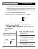
Page 35: ...third party inputs as per below diagram ODU CPU BOARD 12V COM DRM 1 HEAT DRM 2 FAN DRM 3 COMP 2 On the Outdoor Board set Control Source to Third Party Using the MENU and the ENTER Buttons navigate to...

Page 36: ...nly in OD Board Menu follow below steps 1 Using the MENU and the ENTER Buttons navigate to SEt Settings run Unit Operation Indicator Settings 2 If required press MENU to navigate to YES 17 04 Remote O...

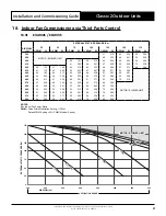
Page 37: ...82 440 42 192 44 213 46 235 48 259 51 281 54 291 450 44 203 46 226 48 250 49 273 52 286 55 296 460 45 213 47 232 49 251 51 271 53 302 70 310 470 47 226 49 243 50 260 53 279 54 296 480 49 228 50 241 52...

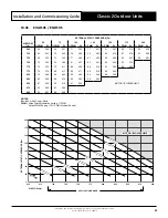
Page 38: ...227 58 262 62 300 66 335 70 375 74 423 79 454 675 57 244 61 282 65 321 69 360 73 400 78 442 83 491 700 60 267 65 305 69 343 73 385 77 428 82 472 87 522 725 64 290 68 328 72 370 77 415 81 454 86 500 92...

Page 39: ...81 437 85 481 90 530 95 579 770 74 370 79 411 84 468 88 516 93 560 98 609 775 75 374 80 417 85 471 89 518 94 564 800 79 398 84 443 89 495 94 546 98 596 825 83 426 88 475 93 525 98 582 850 87 455 92 5...

Page 40: ...8 800 71 315 75 358 80 404 85 457 89 502 93 550 99 610 825 74 340 79 383 84 436 88 482 93 535 97 584 850 78 364 83 413 88 463 92 513 97 568 875 82 390 87 445 92 494 96 549 MOTOR BLOWER LIMIT 900 87 43...

Page 41: ...547 70 593 73 641 75 682 1025 65 476 68 533 70 571 73 625 76 672 80 719 1050 68 511 70 557 73 607 76 659 79 708 85 755 1075 70 534 73 586 76 640 79 697 82 740 1100 73 570 76 624 79 680 82 728 84 750...

Page 42: ...45 93 898 1175 61 528 63 571 65 613 67 660 69 707 72 761 79 827 88 882 97 937 1200 63 551 65 592 67 638 70 707 72 751 74 795 83 864 92 918 1225 65 572 68 640 70 685 72 732 74 780 77 825 86 885 96 958...

Page 43: ...ximum time any system can be opened to atmosphere is 15 minutes Refrigerant Charge Details R 410A Model CRA100S CRA130S CCA130S CRA130T CRA150S CCA150S CRA150T CRA170S CCA170S CRA170T CCA170T CRA200T...

Page 44: ...eing measured and must be insulated in order to obtain correct reading See Diagram Below Use weighing scale when adding or removing refrigerant charge SERVICE GAUGES R 410A REFRIGERANT CONTAINER DISCH...

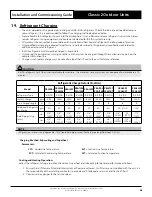
Page 45: ...rging table below there is no need to add remove refrigerant If superheat is lower than minimum it means that liquid refrigerant may be returning to compressor It is necessary to remove refrigerant If...

Page 46: ...621 8 50 10 7 18 332 6 14 1119 2 46 2686 2 49 16 3 17 348 7 15 1154 6 47 2751 8 48 22 2 16 365 2 16 1190 7 48 2818 5 47 28 2 15 382 3 17 1227 5 49 2886 4 46 34 0 14 399 7 18 1265 2 50 2955 5 45 40 9 1...

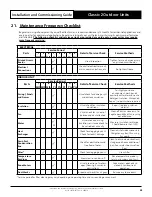
Page 47: ...ot wear loose clothing and any jewellery when working near the fans Wear PPE whenever performing any maintenance procedures Observe all necessary procedures when working on a confined space WARNING Ha...

Page 48: ...al Compartments Ensure consideration is given to the possibility of water entering the electrical compartments during cleaning of the condenser coil Coil Cleaning Procedures Disconnect power to the un...

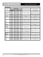
Page 49: ...t accumulation For highly corrosive environment wash panels quarterly with water and neutral detergent solution Wax panels Repair re paint where required Insulation Visual check for insulation conditi...

Page 50: ...ied out annually Measure insulation resistance Should be more than 1M Heat Exchanger Check for clogging by dust Check for leaks damage Clean air inlet side as necessary Straighten any bent fins using...

Page 51: ...LER Name Tel Number Address Site Address Date Installed Model Serial Number CIRCUIT TEMPERATURE SETTINGS Supply Air Temperature o C Return Air Temperature o C Suction Temperature o C Discharge Tempera...

Page 52: ...d Trade Marks of Actron Engineering Pty Limited ActronAir is constantly seeking ways to improve the design of its products therefore specifications are subject to change without notice Document 0525 0...

Reviews: