background image


11

ActronAir 


is constantly seeking ways to improve the design of its products, therefore specifications are subject to change without notice.

Copyright © 2022 Actron Engineering Pty. Ltd.

CP05 & CP10 CONTROL INTERFACE INSTALLATION GUIDE


PROCEDURE FOR ADDRESSING THE MIMIC DISPLAY 

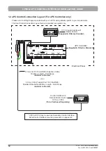
(Refer to ( Diagram in Sec.1.1 page 9 (for CM100)), 

(Diagram in Sec.1.2 page 10 (for uPC))

:

NOTE

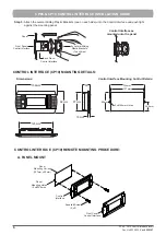
: Where procedures are the same with CP05, only CP10 Control Interface is shown for ease of illustration.


5


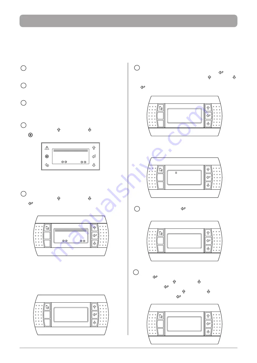
CHANGE the display address to 31 and I/O address 

as   01 (if not set), as follows: Press Enter “

” 

Button to get into the menu, use the “ ” Button or “

” 

Button to change the settings and then press Enter “

” Button again to lock-in the data.


Esc

Prg

Display address

setting ................... :      31

I/O Board  address :      01

       When the Display address change is acknowledged,  

the following screen will appear:


Esc

Prg


 Terminal Config

Press ENTER

to continue


6

 Again, PRESS Enter “

” Button to display the 

Terminal config setting screen below:


Esc

Prg

P: 01  Adr Priv/Shared

Trm1  32        Sh 

Trm2  None   - - 

Trm3  None   - -  Ok?No                                

7

 CHANGE the Trm2 address to 31 by pressing the 

Enter “

” Button two more times, change the 

setting using the “ ” Button or “

” Button and then 

press Enter “ ” Button again. Make that terminal 

as “Shared” using the “ ” Button or “

” Button and 

pressing the Enter “

” Button. 


Esc

Prg

P: 01  Adr Priv/Shared

Trm1  32        Sh 

Trm2  31        Sh

Trm3  None   - -  Ok?No    


1


TURN OFF the unit through the Master Control 

(Control Interface #1). 


2

 DISCONNECT the Master Control Interface from J15 

(for CM100), CONTROL INTERFACE (for uPC).


3

 CONNECT the Remote Mimic Control (Control 

Interface #2) into J15 (for CM100), CONTROL 

INTERFACE (for uPC).


4a

 (

CP05 Procedure

): 

       PRESS the Up “ ” arrow, Down “

” arrow and Enter     

” keys together for 5 seconds on the Home Screen. 


CP05 Remote Mimic Control

(Control Interface #2)


Return Temp:

23.7

o

C

16.5

o

C


Supply Temp:


Comp


Rev Vlv


 9:30     Unit: On               Auto


4b

 (

CP10 Procedure

): 

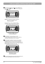
       PRESS the Up “ ” arrow, Down “

” arrow and Enter 

” buttons together for 5 seconds on the Home 

Screen.    


Esc

Prg


Return Temp:

23.7

o

C

16.5

o

C


Supply Temp:


Comp


Rev Vlv

  9:30    Unit: On           Auto

CP10 Remote Mimic Control

(Control Interface #2)


 The screen will show the Default Display address and 

I/O board address. Ensure the Display address setting 

is 32, which is the preset, and I/O board address is 01.


Esc

Prg

Display address

setting ................... :      32

I/O Board  address :      01

Summary of Contents for CP05

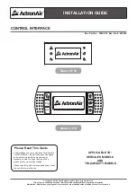
Page 1: ...TION GUIDE CONTROL INTERFACE Please Read This Guide Congratulations on your purchase of an ActronAir Control Interface This device has been designed and manufactured with the highest quality standard in mind We hope that you will be satisfied with your excellent choice Please read this guide thoroughly and keep it near the unit for future reference Model CP05 Model CP10 Esc Prg APPLICABLE TO HERCU...

Page 2: ...e to the unit and void your warranty 2 2 Turn Off power from mains supply by removing fuse or switching the circuit breaker to the Off position Turn Off power from mains supply by removing fuse or switching the circuit breaker to the Off position before installation or servicing this control interface before installation or servicing this control interface 3 3 Follow sound Lock Out Tag Out procedu...

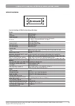
Page 3: ...ximum pLAN length 500m with 6 Core 3 Pair Twisted Pair 7 0 20 AWG24 Shielded Data Cable Max OD Controller terminal distance Wires must be approved for 75o C temp 50m with 6 Core Flat 7 0 12 AWG28 Telephone Cable 500m with 6 Core 3 Pair Twisted Pair 7 0 20 AWG24 Shielded Data Cable Materials Transparent front panel cover glass frame Transparent polycarbonate Charcoal grey container back piece Polyc...

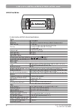
Page 4: ...a bus layout with branches not exceeding 5m Maximum pLAN length 500m with 6 Core 3 Pair Twisted Pair 7 0 20 AWG24 Shielded Data Cable Max OD Controller terminal distance 50m with 6 Core Flat 7 0 12 AWG28 Telephone Cable 500m with 6 Core 3 Pair Twisted Pair 7 0 20 AWG24 Shielded Data Cable Materials Transparent front panel cover glass frame Transparent polycarbonate Charcoal grey container back pie...

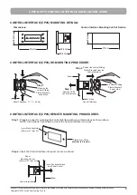
Page 5: ...section T Step 1 Remove CP05 Control Interface Panel PUSH 2 x Lateral Sliding Plastic Brackets 1 each side Back Piece Control Interface Pull out the Lateral Sliding Plastic Brackets from the Control Interface Step 3 Step 2 CONTROL INTERFACE CP05 REMOTE MOUNTING PROCEDURES Step 1 Prepare a panel for mounting the Control Interface with cut out dimensions as shown above NOTE Use a Blank Cover Plate t...

Page 6: ...PUSH Panel Back Piece Control Interface PUSH 2 x Lateral Sliding Plastic Brackets 1 each side Front Panel Control Interface CONTROL INTERFACE CP10 MOUNTING DETAILS Dimensions Control Interface Mounting Cut Out Details 2 x ø2 5mm Holes 127mm 134mm 34 5mm 69mm 18mm 30 67mm Esc Prg 82mm 156mm 125mm CONTROL INTERFACE CP10 REMOTE MOUNTING PROCEDURE A PANEL MOUNT Front Cover Control Interface Panel Moun...

Page 7: ...ly Front Cover Control Interface Control Interface Wall Mount Cover Control Interface Wall Mounting Cut Out 50mm x 70mm Suggested Step 1 Remove the Front Cover from the Control Interface assembly Step 2 Remove the Back Cover and the Gasket from the Control Interface assembly Step 3 Install the Control Interface onto the wall using mounting bracket and wall mount cover as shown below Tab Tab Use a ...

Page 8: ...below RJ12 Plug Installer to Provide RJ12 Plug Installer to Provide VIEW FROM CABLE END VIEW FROM CABLE END 6 Core 3 Pair Twisted Pair 7 0 20 AWG24 Shielded Data Cable 200 Max Length Field Scope Installer to Provide 6 5 4 3 2 1 6 5 4 3 2 1 6 Core Flat 7 0 12 AWG28 Telephone Cable 50m Max Length Field Scope Installer to Provide See RJ12 Terminal Connections A below RJ12 Plug Installer to Provide RJ...

Page 9: ... TX 12 Vdc 13 GND 14 6 Core 3 Pair Twisted Pair 7 0 20 AWG24 Shielded Data Cable 200 Max Length Field Scope Installer to Provide 6 Core Flat 7 0 12 AWG28 Telephone Cable 50m Max Length Field Scope Installer to Provide or CM100 Controller Supplied Fitted as Standard Esc Prg Return Temp 23 7 o C 16 5 o C Supply Temp Comp Rev Vlv 9 30 Unit On Auto Esc Prg Return Temp 23 7 o C 16 5 o C Supply Temp Com...

Page 10: ...t 7 0 12 AWG28 Telephone Cable 50m Max Length Field Scope Installer to Provide or uPC Controller Supplied Fitted as Standard Esc Prg Return Temp 23 7 o C 16 5 o C Supply Temp Comp Rev Vlv 9 30 Unit On Auto Esc Prg Return Temp 23 7 o C 16 5 o C Supply Temp Comp Rev Vlv 9 30 Unit On Auto CP05 or CP10 may be used as Secondary Control Interface Refer Control Interface mounting procedure on pages 6 8 1...

Page 11: ...Trm2 address to 31 by pressing the Enter Button two more times change the setting using the Button or Button and then press Enter Button again Make that terminal as Shared using the Button or Button and pressing the Enter Button Esc Prg P 01 Adr Priv Shared Trm1 32 Sh Trm2 31 Sh Trm3 None Ok No 1 TURN OFF the unit through the Master Control Control Interface 1 2 DISCONNECT the Master Control Inter...

Page 12: ...mp 23 7 o C 16 5 o C Supply Temp Comp Rev Vlv 9 30 Unit On Auto CP10 Remote Mimic Control Control Interface 2 9 DISCONNECT the Remote Mimic Control Control Interface 2 from CM100 J15 for CM100 CONTROL INTERFACE for uPC terminal 10 RE CONNECT the Master Control Control Interface 1 back into CM100 J15 for CM100 CONTROL INTERFACE for uPC terminal and check whether the setting changes reflect both way...

Page 13: ...THIS PAGE WAS INTENTIONALLY LEFT BLANK ...

Page 14: ...THIS PAGE WAS INTENTIONALLY LEFT BLANK ...

Page 15: ...THIS PAGE WAS INTENTIONALLY LEFT BLANK ...

Page 16: ... Copyright 2016 Actron Engineering Pty Limited ABN 34 002767240 Registered Trade Marks of Actron Engineering Pty Limited Document 0525 035 Issue Date 03 2022 Refrigerant Trading Authorisation No AU06394 ...

Reviews: