5
ActronAir
is constantly seeking ways to improve the design of its products, therefore specifications are subject to change without notice.
Copyright © 2022 Actron Engineering Pty. Ltd.
CP05 & CP10 CONTROL INTERFACE INSTALLATION GUIDE
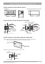
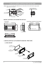
CONTROL INTERFACE (CP05) MOUNTING DETAILS:
Dimensions:
Control Interface Mounting Cut-Out Details:
34.6mm
76mm
38.4mm
34.4mm
29mm
71mm
CONTROL INTERFACE (CP05) DE-MOUNTING PROCEDURE:
Panel Thickness: T = 1.2 - 6.0mm
PUSH
Press-on the
Lateral Sliding
Plastic Brackets’
mid section
T
Step 1
Remove CP05
Control Interface
Panel
PUSH
2 x Lateral Sliding
Plastic Brackets
(1 each side)
Back Piece-
Control Interface
Pull-out the Lateral Sliding
Plastic Brackets from the
Control Interface
Step 3
Step 2
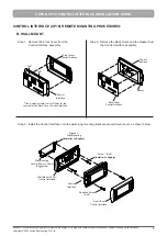
CONTROL INTERFACE (CP05) REMOTE MOUNTING PROCEDURES:
Step 1:
Prepare a panel for mounting the Control Interface with cut-out dimensions as shown above.
NOTE: Use a Blank Cover-Plate to mount the Control Interface into a wall.
BlankCover- Plate
(Installer to Provide)
Cut-out
Mounting Hole
(29mm H x 71mm W)
Step 2:
Insert the Control Interface into panel cut-out, as shown:
Panel
Panel
Mounting Cut-out
(29mm H x 71mm W)
Control Interface
Insert Control Interface
unto Panel Cut-out

