6
CP05 - CP10 Control Interface Insert
Doc. No.0525-035
Ver. 6 220307
CP05 & CP10 CONTROL INTERFACE INSTALLATION GUIDE
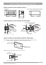
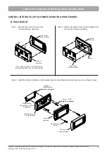
Step 3:
Attach the Lateral Sliding Plastic Brackets (one on each side) unto the Control Interface and push tight
against the mounting panel:
Control Interface as
mounted unto the panel
PUSH
Panel
Back Piece-
Control Interface
PUSH
2 x Lateral Sliding
Plastic Brackets
(1 each side)
Front Panel-
Control Interface
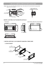
CONTROL INTERFACE (CP10) MOUNTING DETAILS:
Dimensions:
Control Interface Mounting Cut-Out Details:
2 x
ø
2.5mm Holes
127mm
134mm
34.5mm
69mm
18mm
30
67mm
Esc
Prg
82mm
156mm
125mm
CONTROL INTERFACE (CP10) REMOTE MOUNTING PROCEDURE:
A. PANEL MOUNT
Front Cover
Control Interface
Panel
Mounting Holes
(2 x
ø
2.5mm)
Panel
Mounting Cut-out
(127mm x 69mm)
Supplied Screw
(2-off)
Control
Interface

