9
ActronAir
®
is constantly seeking ways to improve the design of it’s products, therefore specifications are subject to change without notice.
Copyright © 2016 Actron Engineering Pty. Ltd.
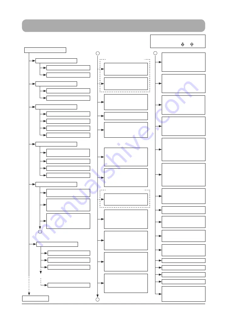
MENU TREE DIAGRAM
CONSUMER / END USER MENU
NOTE
:
To toggle (scroll) "Up" or "Down" from
existing menu, press “ ”
or
“ ” Button.
Main Menu
A. On /Off Unit
B. Setpoint
C. Mode of Operation
D. Clock
E. Status
Unit “ON”
Room Temp / RH Setpoint
Cool Only
Special 12 Days
Day / Date / Hour
Enable Scheduler / Night Mode
Return Temp / Supply Temp
Outside Temp
Cond Temp 1 / Cond Temp 2
Low Press 1 / High Press 1
Low Press 2 / High Press 2
Fan Only
Day Light Saving Time
Unit “OFF”
Filter Pressure Alarm Setpoint
Heat Only
Auto Change Over
After Hour Operation Duration
B
Log 1 - Recent Alarm
Log 3 - Recent Alarm
Log 100 - Recent Alarm
Up To
Log 2 - Recent Alarm
F. Alarm History
To Service Menu
Supply Pressure
Supply Volume
Filter Pressure
Disch Temp 1 / Disch Temp 2
C
S1 Probe Evap Press / Temp
Defrost Count:
Compressor 1 / Compressor 2
S3 Probe Evap Press / Temp
S2 Probe Suction Temperature
S4 Probe Suction Temperature
Power Information:
Total Power
Supply Fan1 / OD Fan1 / Comp1
Supply Fan2 / OD Fan2 / Comp2
S1 Probe Status
S2 Probe Status
S3 Probe Status
S4 Probe Status
Damper Status
Min. Outside Position Internal
Damper Command
Valve A
Status / Opening / Position
Cool. Capacity / Superheat
Valve B
Status / Opening / Position
Cool. Capacity / Superheat
VSD 1 Status / Run
Alarms / Speed Status
Request / Feedback
Dissip. temp. / DC volyage
Motor data:
Speed / Voltage / Current
VSD 2 Status / Run
Alarms / Speed Status
Request / Feedback
Dissip. temp. / DC volyage
Motor data:
Speed / Voltage / Current
Outdoor Fan 3 Status
Actual / Max Speed
DC Voltage / DC Current
Output Power
Elec. Temperature
Outdoor Fan 2 Status
Actual / Max Speed
DC Voltage / DC Current
Output Power
Elec. Temperature
Outdoor Fan 4 Status
Actual / Max Speed
DC Voltage / DC Current
Output Power
Elec. Temperature
Outdoor Fan 1 Status
Actual / Max Speed
DC Voltage / DC Current
Output Power
Elec. Temperature
Status Heat Reclaim
Supply-Room
ReClaim D_Out / Mech Heat en.
*
Condenser Fan1 = Fan1 & Fan 2
**
Condenser Fan2 = Fan3 & Fan 4
Supply Fan 1 Status
Actual / Max Speed
DC Voltage / DC Current
Output Power
Elec. Temperature
Supply Fan 3 Status
Actual / Max Speed
DC Voltage / DC Current
Output Power
Elec. Temperature
Supply Fan 2 Status
Actual / Max Speed
DC Voltage / DC Current
Output Power
Elec. Temperature
Supply Fan 4 Status
Actual / Max Speed
DC Voltage / DC Current
Output Power
Elec. Temperature
*
Condenser Fan 1 %
**
Condenser Fan 2 %
Supply Fan %
Economy Cycle %
Compressor 1: On / Off
Comp Request 1: %
Rev. Valve 1: On / Off
Crank Heater 1: On / Off
ReHeat Valve 1: On / Off
Compressor 2: On / Off
Comp Request 2: %
Rev. Valve 2: On / Off
Crank Heater 2: On / Off
ReHeat Valve 2: On / Off
B
C
DRM1 DRM2 DRM3
Remote On / Off
HP 1 / LP 1 Switch Ok / Fault
LP 1 Switch Bypass
HP 2 / LP 2 Switch Ok / Fault
LP 2 Switch Bypass
RS485 Outside Probe
Temperature / Humidity
Dew Point / Enthalpy
RS485 Room Probe
Temperature / Humidity
Dew Point / Enthalpy
If Enabled in Service Manual
If Enabled in Service Manual


