Installation Guide
Easyconnect App
7
Installation Guide - Easyconnect App
Document: 9590-4009
Ver. 2 201126
3. Insert the supplied Easyconnect Wi-Fi USB into the port at the back of the
Smart Port Reciever. (See Figure 4-4)
8
Fig 4-5
4. INSTALLATION METHOD
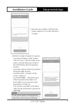
4.Remove the upper part of the smart port
For exposed mounting, fasten
the back plate on the wall with
the 3 screws (M4×20) and plugs.
(Fig.4-6)
6. Insert the smart kit with slightly strength into the main PCB
of the smart port .(Fig.4-7)
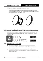
5. Fasten the back plate of the smart port
Slots
Insert a slot screwdriver into the slots in the
lower part of the smart port (2 places), and
remove the upper part of the smart port.
(Fig.4-5)
Fig 4-6
Back plate
Screws (M4×20)
Fig 4-7
Figure 4-4
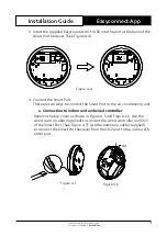
4. Connect the Smart Port:
There are two ways to connect the Smart Port to the air conditioning unit.
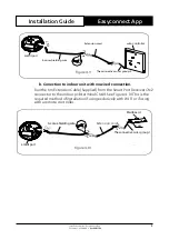
a. Connection to indoor unit and wired controller
Remove the top cover as shown in Figure 4-5 and Figure 4-6. Use the
wired control cable (supplied) to connect the wired controller and CN3
of the Smart Port. (See Figure 4-7). Use the extension cable (supplied)
to connect the Smart Port Receiver from the CN2 port to the indoor PCB
CN40 port.
11
4. INSTALLATION METHOD
NOTE:
Connection for wired control function by KJR-120C/TF-E
KJR-120G2/TFBG-E
9. Connect the smart port to the wire controller
(
if needed
)
Fig 4-12
①
Remove the top cover from the gap between the top cover
and bottom by a tool with flat head. (See Fig.4-12)
②
Use the connective cable to connect the wire controller
and CN3 of the smart port. (See Fig.4-13)(refer to the Wire
controller manual for details)
Fig 4-13
CN3
Figure 4-5
Figure 4-6
CN3

