Installation Guide
Easyconnect App
9
Installation Guide - Easyconnect App
Document: 9590-4009
Ver. 2 201126
7
4. INSTALLATION METHOD
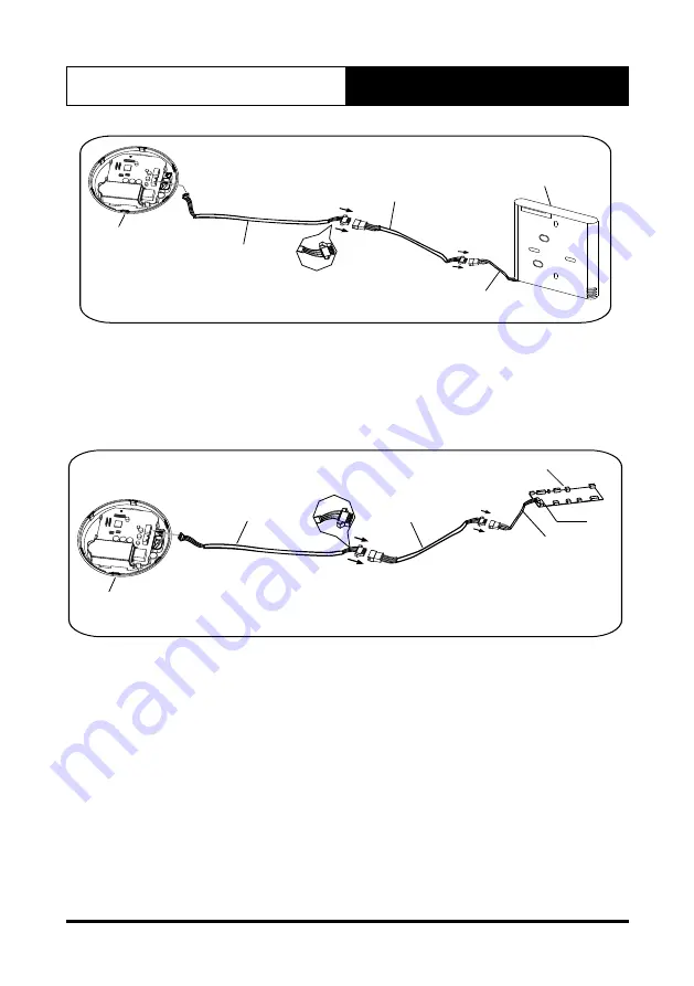
Fig 4-4
smart port
CN
3
4-core shielding wire
Extension cord
The connective wires group-2
wire controller
If you want to use both wire controller and WIFI control at the
same time , you can use the CN3 port on the smart port
terminal to connect the wire controller ( shown as Fig 4-4).
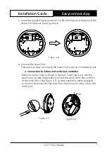
Figure 4-9
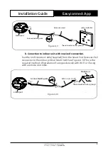
b. Conection to indoor unit with no wired connection.
Run the 6m Extension Cable (Supplied) from the Smart Port Receiver CN2
connector to the indoor pcb terminal CN40. See Figure 4-10.This is the
required method of installation if using exclusively with Wi-Fi or if using
with a remote controller.
6
4. INSTALLATION METHOD
Please confirm the connective wires group-1 (shown in
Fig 4-3) , one side is connected to the port CN40 on indoor
main PCB board , another side is plugged into CN40 on the
WIFI smart port terminal . On some case , when you need
a extension cord , please contact your distributor .
Fig 4-3
3.Wiring figure
If want to extent the wire ,please use extension cord
(purchased separately) . (See Fig.4-3)
smart port
Mainboard
4-core shielding wire
Extension cord
(purchased separately)
The connective wires group-1
CN40
CN40
Figure 4-10
Extension cord
CN2

