Installation and Commissioning Guide
Hercules Package Unit
21
Installation and Commissioning Guide - Hercules Package Unit
Doc. No.0525-021
Ver. 21 221110
09. Condensate and Safety Tray Drainage Instructions
Suggested Minimum Slope To Ensure Correct Drainage
FRONT VIEW
SIDE VIEW
TOP VIEW
Outdoor Section Condensate Drain
must be run separately from the
Indoor Section Condensate Drain
Ensure Drain Pipes
slope down at a
minimum
of 10 mm per metre
Condensate Drain
Brass Connector
Ø 31.8 mm (1-1/4”)
BSP Female Thread
Condensate Drain
Coupling Ø 31.8 mm
(1-1/4”)
BSP Female Thread
(1 x each side)
OUTDOOR COIL
OUTDOOR COIL
IND
O
OR C
OIL
COMP
COMP
PL
UG F
AN
PL
UG F
AN
Ensure Drain Pipes slope down from the
unit at a minimum of 10 mm per meter
A
Suggested Drain Trap Details
Ensure Drain Pipe slopes down
from the unit at a minimum of
10 mm per meter
DETAIL A
The top of the Trap must be
125 mm below the top of the
Evaporator Drain Connection
50 mm
4 X PVC ELBOW
Install a T-Piece
as an Air Vent
for long drain runs
CLAMP
BANDS
Evaporator
Condensate Tray
The top of the Vent must be 50
mm higher than the top of the
Evaporator Condensate Tray
250 mm or high
enough to maintain
positive Air Seal
Condensate Drain
Connection
TRAP
Clear Plastic
Inspection
Tube
125 mm
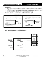
IMPORTANT NOTES
1. Parts for the Condensate Trap are not supplied with the unit.
2. Refer to Unit Dimensions page of the Technical Selection Catalogue for specifi cations of drain connectors.


