28
Installation and Commissioning Guide
Hercules Package Unit
Installation and Commissioning Guide - Hercules Package Unit
Doc. No.0525-021
Ver. 21 221110
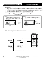
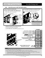
Item
Description
Maximum Cable Length
1 to 2
Outdoor CM100 to Optional ActronAir CP05 / CP10 Control Interface (Dual Control)
50m / 200m - See Note D
1 to 3
Outdoor CM100 to Room Air Temp Sensor (NTC Sensor Input Cable Size 0.5mm2 / 1.0mm2)
50m / 100m
1 to 4 Outdoor CM100 to Room CRH-S Sensor
200m - See Note E
1 to 5
Outdoor CM100 to Duct CRH-D Sensor
200m - See Note E
1 to 6 Outdoor CM100 to ActronAir CP10 (Remotely re-located Factory Supplied Control Interface)
50m / 200m - See Note D
1 to 7
Outdoor CM100 to Third Party Control
Refer to Third Party Control
Supplier
*
Room Air Sensor is factory supplied with 6m cable as standard. Sensor may need adjustment for longer cable lengths.
**
Do not extend the factory supplied data cable when re-locating the Control Interface. Replace the cable with a single length of either of the data cables specified
above.
NOTES
A. Diagram shown above is a general presentation only. Refer to individual unit wiring diagram for complete wiring connection details.
B. Long cable runs beside supply mains or TV antenna cables should be avoided where possible.
C. Return Air Sensor needs to be installed by the installer specific to site requirements.
D. Suggested Maximum Cable Length: 50 m when using Flat Telephone Cable / 200 m when using 6 Core (3Pair)Twisted Pair Shielded Data Cable.
E. For compliance with EMC requirements, connect screen wire to Terminal 14 on the Control Panel. For compliance with EMC requirements, connect
screen wire to the GND Terminal and to an earth if G0-Earth connection is required.
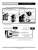
14. Data Cable and RJ12 Plug Preparations:
Option 1 - Data Cable with RJ12 plug at both end:
S
ee RJ12 Terminal Connections
B below.
RJ12 Plug
(
Installer to Provide
)
RJ12 Plug
(
Installer to Provide
)
VIEW
FROM CABLE END
VIEW
FROM CABLE END
6 Core (3 Pair) Twisted Pair 7/0.20 (AWG24) Shielded Data Cable
200 m Max. Length - Field Scope
(
Installer to Provide
)
6
5
4
3
2
1
6
5
4
3
2
1
6 Core Flat 7/0.12 (AWG28) Telephone Cable
50 m Max. Length - Field Scope
(
Installer to Provide
)
S
ee RJ12 Terminal Connections A
below.
RJ12 Plug
(
Installer to Provide
)
RJ12 Plug
(
Installer to Provide
)
VIEW
FROM CABLE END
VIEW
FROM CABLE END
6
5
4
3
2
1
6
5
4
3
2
1
RJ12 Terminal Connections A:
• Terminal 3:- Connect to RX-/TX- on the connector block.
• Terminal 4:- Connect to RX+/TX+ on the connector block.

