34
Installation and Commissioning Guide
Hercules Package Unit
Installation and Commissioning Guide - Hercules Package Unit
Doc. No.0525-021
Ver. 21 221110
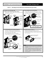
15.02.04. Dual Control Interface Connection Procedure
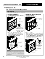
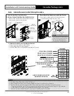
1. Open Access-Door Control Section
2. Remove Access Panel-Electrical Isolator Section
• Perform steps 1-2 of Main Supply Cable Installation section to
gain access to control panel.
1
ACCESS
DOOR -
CONTROL
QUARTER
TURN LOCKS
ACCESS
DOOR
CONTROL
CONTROL
INTERFACE
2
ACCESS PANEL
ELECTRICAL
LOCK
SCREWS
CONTROL
PANEL
CM100
CONTROLLER
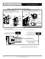
3. Connect Field AWG24 Cable to 4-Way Connector-A
• Thread the Field AWG24 Cable through the unit and connect
to the Terminal Block as shown above.
GND
+Vdc
RX+/TX+
RX-/TX-
14
12
13
11
Refer cable routing procedures on previous subsection.
TERM
GND
+Vdc
RX+/TX+
RX-/TX-
WIRES from
CM100
Controller
WIRES to
Control Interface #2
TERMINAL
BLOCKS
FIELD AWG24
TWISTED PAIR
SHIELDED CABLE
(Installer to Supply)
CM100
CONTROLLER
4. Connect Control Interface #2
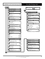
• Connect the Control Interface #2 (secondary control interface), as shown in the schematic diagram below:
CONTROL INTERFACE # 2
- Remote Mimic Display
CP10 or CP05
(To be Purchased Separately)
CP10 CONTROL INTERFACE # 1
(Supplied and Fitted as Standard)
input 24V +10% -15% 50-60Hz / 28-36V
max power: 28W/20W
BMS Card
J11 BMS2
GND
Tx/Rx
J14pLAN
Vout
J9 FBus1
J10
J15
J12
1
U8
U9
U10
+V
dc
+5VR
GND
J5
DI7H
DI7
DI7C
DI8
DI8H
J25
GND
Y1
Y2
Y3
J6
U1
U2
U3
GND
J2
D11
D12
D13
D14
GND
J7
U6
U7
+V
dc
+5VR
GND
J4
46
U5
+V
dc
+5VR
GND
J3
NO1
NC1
NC1
J16
Out3
C2
J18
Out4
C2
J19
Out5
C2
J20
NO6
C6
J22
NO7
C7
J23
NO8
C8
J24
C2
V-IN
J21
Out2
C2
J17
C11
NO11
NO12
NO13
C11
J28
NO9
C9
NC9
NO10
C10
NC10
J27
J8
2
Y4
Y5
U11
GND
U12
GND
D9
D10
DI9C
J26
G
G0
J1
cm
100
®
J13
GND
J29FBus2
Tx/Rx
RX+ / TX+
11
RX
- / TX
-
12
+V
dc
13
GND
14
Esc
Prg
Return T. :
16.3
o
C
22.2
o
C
Supply T. :
Comp
Rev Vlv
9:30 Unit: OFF by KEY
Esc
Prg
Return T. :
16.3
o
C
22.2
o
C
Supply T. :
Comp
Rev Vlv
9:30 Unit: OFF by KEY
6 CORE (3 PAIR) TWISTED PAIR 7/0.20
(AWG24) SHIELDED DATA CABLE 200 m
Max. Length - Field Scope
(Installer to Provide)
Refer to Dual Control Interface Connection Procedure
for configuration and addressing of Secondary Control Interface
CM100 CONTROLLER
(Supplied and Fitted as Standard)


