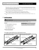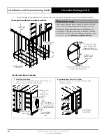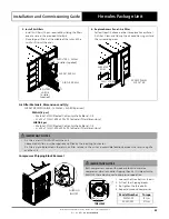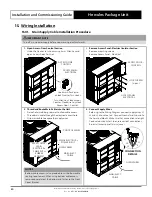
Installation and Commissioning Guide
Hercules Package Unit
35
Installation and Commissioning Guide - Hercules Package Unit
Doc. No.0525-021
Ver. 21 221110
16. Return Air Temperature Sensor Installation
Introduction
Return Air Temperature Sensor location will vary based on individual site installation requirements, hence the sensor is not
fitted to your air conditioning unit. It is supplied and packed together with this installation guide inside the Installation Guide
/ Warranty Pack envelope. The return air sensor comes standard with 6m lead cable. It will need installation and calibration
by the installer prior to commissioning of your air conditioning unit.
Installation Instructions:
1. Install the return air temperature sensor inside the return air duct or inside the room, just below the return air grille.
2. Ensure that the sensor is located where the return air is not affected by other heat source.
3. Return air temperature sensor must be properly secured in the chosen location.
4. Sensor cable should be routed securely and not to be exposed to sunlight, rain, dust and other contaminants.
5. Keep sensor cable away from high voltage cables.
NOTE
• The provided Return Air Temperature sensor is an ActronAir duct bead type sensor. A wall type sensor is also available
as an option (ActronAir Part Number LM-RS).
• For longer installation requirements, it is possible to extend the provided 6m sensor lead cable with an extension
cable. The extension cable MUST comply to the specification below and installer MUST offset the sensor reading.
Specifications - Sensor Lead Cable
Item
Distance
Up to 50m
Up to 100m
NTC (Sensor Cable) *
0.5mm2
1.0mm2
* Extension cable must be screened cable with the screen connected to ground terminal G0 (J1) of the 24VAC
controller supply.
Use only the provided ActronAir duct bead sensor or the optional wall sensor (LM-RS).
Use of 3rd party sensors are not allowed as they are not tested with ActronAir air conditioning unit.
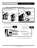
RETURN AIR
TEMPERATURE SENSOR
GND
RETURN AIR
TEMP. SENSOR
Connect sensor wires
to terminals # 18 and 20
15
16
17
18
19
20
21
22
23
24
FA
UL
T C
O
M
FA
UL
T NC
FA
UL
T NO
RE
TURN AIR SENSOR
IN-F
AN DE
M
AND
0 - 10V
GND
RE
M
O
TE ON/
OFF
DEHUMIDIF
Y ON
(2
4V
A
C
)
HE
A
T ON (2
4V
A
C
)
24V
A
C OUT
TERMINAL
IMPORTANT NOTE
For units with Optional Economy Cycle, Return Air Temperature Sensor needs to be installed and located by the installer specific
to site requirements.


