36
Installation and Commissioning Guide
Hercules Package Unit
Installation and Commissioning Guide - Hercules Package Unit
Doc. No.0525-021
Ver. 21 221110
Offset Instructions:
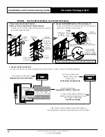
1. Read the return air temperature from the control interface (the installed return air temp sensor is measuring the return
air temp.
2. Using a different temperature measuring device, measure the actual air temperature next to installed return air sensor.
3. Get the difference to calibrate the installed return air temperature sensor via service menu:
Main Menu
G. Service
Gf. Service settings
Gfb. Probe Adjustment
Gfb3
(Password Protected)
Example 1:
If the actual measured room temperature is 2.0°C
higher than control interface reading, then adjust the
offset to +2.0°C.
Probe adjust. Gfb3
Room NTC cal:
Supply NTC cal:
Cond. 1 NTC cal:
Cond. 2 NTC cal:
Outside NTC cal:
+2.0°C
0.0°C
0.0°C
0.0°C
0.0°C
CP10
Probe Adjustment Display
Enter return
air temp
offset here
Example 2:
If the actual measured room temperature is 2.0°C
lower than control interface reading, then adjust the
offset to -2.0°C
Probe adjust. Gfb3
Room NTC cal:
Supply NTC cal:
Cond. 1 NTC cal:
Cond. 2 NTC cal:
Outside NTC cal:
-2.0°C
0.0°C
0.0°C
0.0°C
0.0°C
CP10
Probe Adjustment Display
Enter return
air temp
offset here
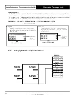
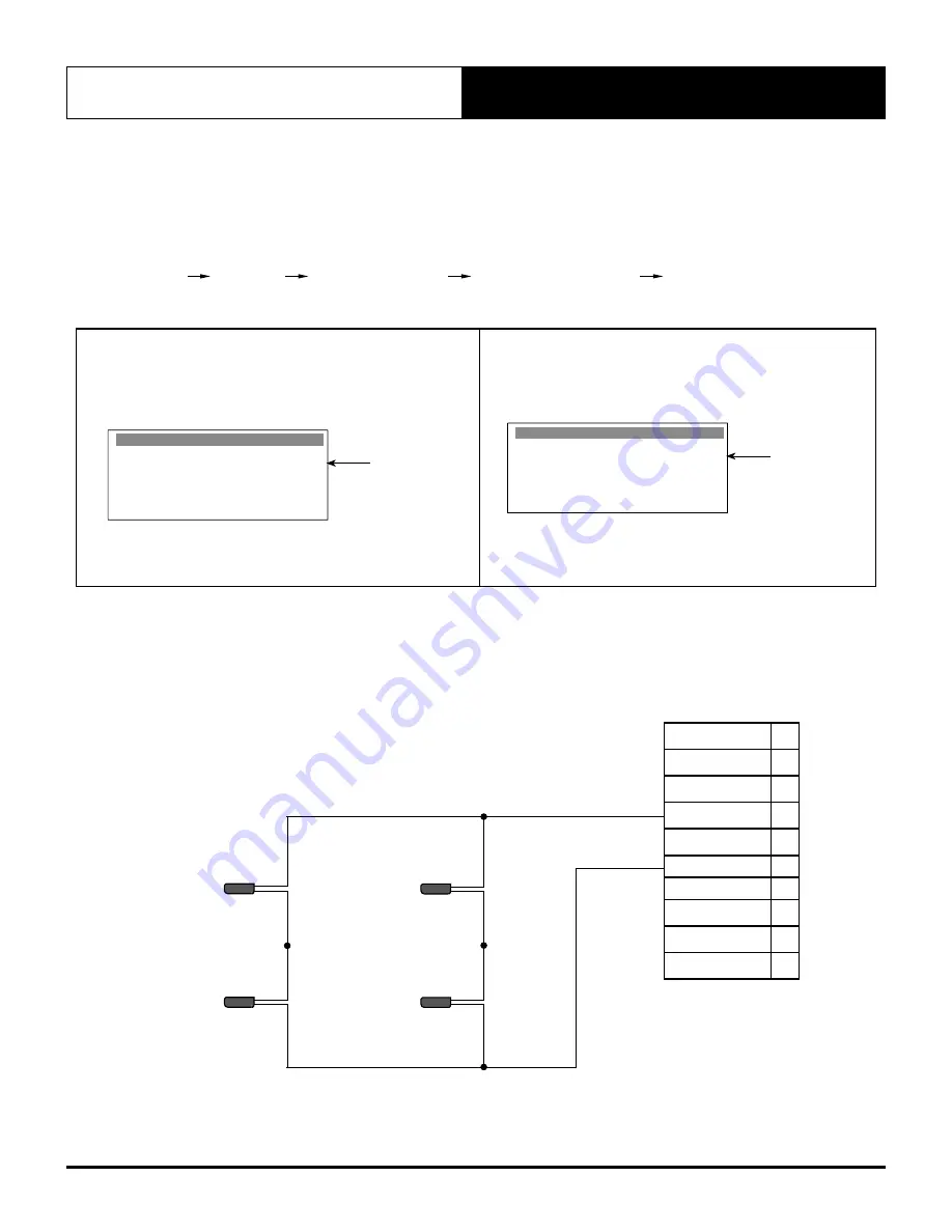
16.01. Averaging Return Air Temperature Sensors
RETURN TEMP
NTC SENSOR 1
RETURN TEMP
NTC SENSOR 3
RETURN TEMP
NTC SENSOR 2
RETURN TEMP
NTC SENSOR 4
15
16
17
18
19
20
21
22
23
24
FAULT COM
FAULT NC
FAULT NO
RETURN AIR
SENSOR
IN-FAN DEMAND
0 - 10V
GND
REMOTE ON/OFF
DEHUMIDIFY ON
(24VAC)
HEAT ON (24VAC)
24VAC OUT
TERMINAL


