background image


17

Installation and Commissioning Guide

Mini Cassette Split System

Installation and Commissioning Guide - Mini Cassette 2 Split System

Doc. No. 9590-5010  

Ver. 1  211217

13.  Wiring

Safety Precautions

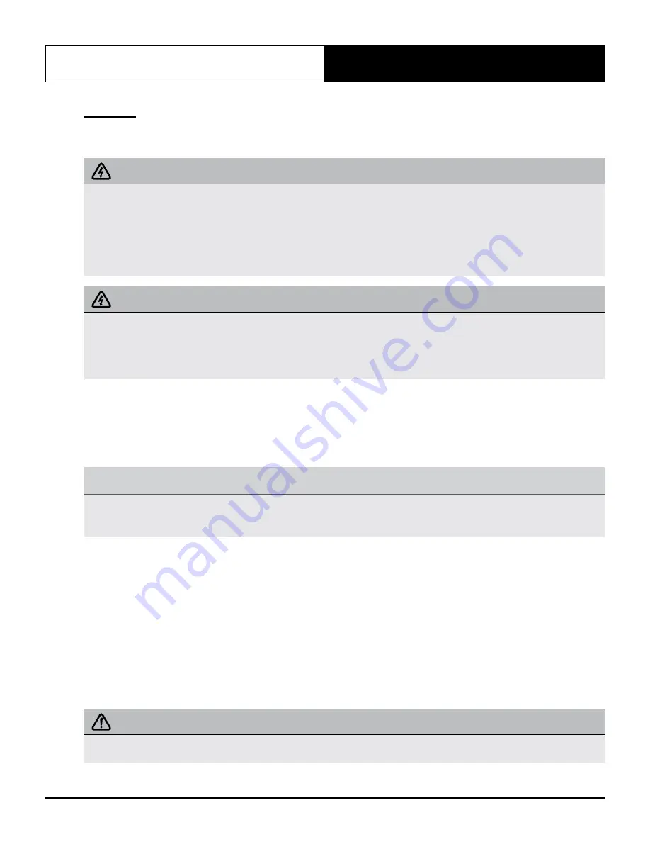
  WARNING

•  Be sure to disconnect the power supply before working on the unit.
•  All electrical wiring must be done according to local and national regulations.
•  Electrical wiring must be done by a qualified technician. Improper connections may cause electrical malfunction, injury 

and fire.

•  Connect the power cable to the terminals and fasten it with the clamp.
•  Make sure that all wiring is done correctly and the control board cover is properly installed. Failure to do so can cause 

overheating at the connection points, fire, and electrical shock.

  CAUTION

•  Connect the outdoor wires before connecting the indoor wires.
•  Make sure you earth the unit. Improper earthing may cause electrical shock.
•  DO NOT connect the unit with the power source until all wiring and piping is completed.
•  Make sure that you do not cross your electrical wiring with your signal wiring, as this can cause distortion and 

interference.

Follow these instructions to prevent distortion when the compressor starts:


The unit must be connected to its individual sub-circuit. Ensure sub-circuit mains are of recommended size to ensure 
minimal voltage drop at supply terminals.


No other equipment should be connected to the same sub-circuit as the A/C unit.


The unit’s power information can be found on the rating sticker on the product.


TAKE NOTE OF FUSE SPECIFICATIONS

The air conditioners circuit board (PCB) is designed with a fuse to provide overcurrent protection. The specifications of  the 
fuse is printed on the circuit board, T3.15A/250VAC.  
For the units with R-32 refrigerant , only the blast-proof ceramic fuse can be used.

Indoor Unit Wiring

1.  Prepare the cable for connection

a.  Using wire strippers, strip the outer insulation from both ends of signal cable.
b.  strip the insulation from the ends of the internal wires.
c.  Using a wire crimper, crimp fork-lugs on the ends of the wires.

2.  Remove the cover of the electric control box on your indoor unit.
3.  Connect the fork-lugs to the terminals. Match the wire  colors/labels with the labels on the terminal block, and firmly 

screw the lug of each wire to its corresponding terminal. Refer to the Serial Number and Wiring Diagram located on 
the cover of the electric control box.

4.  Clamp down cable with the designated cable clamp to secure it in place. The cable should not be loose, and should 

not pull on the lugs.

5.  Reinstall the electric box cover.

 CAUTION

•  While connecting the wires, please strictly follow the  wiring diagram.
•  The refrigerant circuit can become very hot. Keep the interconnection cable away from the copper tube.

Summary of Contents for MRE-035CS

Page 1: ...this manual carefully before installing or operating your air conditioning unit Make sure to save this manual for future reference CAUTION Outdoor unit is charged with flammable refrigerant safety che...

Page 2: ...RICIAN DIY DIY DIY ALL ELECTRICAL WORK MUST BE PERFORMED BY A LICENSED ELECTRICIAN FOR COMPLIANCE WITH QUEENSLAND ELECTRICAL SAFETY REGULATIONS 2013 This refers to electrical works only READ SAFETY PR...

Page 3: ...ards All electrical wiring must be in accordance with current electrical authority regulations and all wiring connections to be as per electrical diagram provided with the unit 03 General Information...

Page 4: ...erformance capacity that are among the best in the market the ActronAir air conditioning units provide the solution for the reduction of energy consumption CO2 emission high fuel dependency and high n...

Page 5: ...jury Secure the fans against accidental contact Always wear appropriate PPE and remove any dangling jewellery and protect long hair by wearing a cap Ensure that no loose clothing can be caught entangl...

Page 6: ...and minimize vibration transfer through the foundation Ensure that all anti vibration rubbers are rated to provide stable support without impairing the unit s structural integrity Diameter or width of...

Page 7: ...s Owner s manual PRELIMINARY DATA ONLY Ver 1 01 211129 THIS LABEL TO BE REMOVED ON SIGN OFF That s better That s Actron Mini Cassette 2 Split System Air Conditioner IMPORTANT NOTE Please read this man...

Page 8: ...ni Cassette 2 Split System Doc No 9590 5010 Ver 1 211217 07 Installation Overview Installation Order Refer to Multi Elite Installation Manual Outdoor Unit for more details Leak Testing Air Evacuation...

Page 9: ...ng personal injury unit and property damage or death DO NOT install the indoor unit in the bathroom or laundry room as excessive moisture can short the unit and corrode the wiring CAUTION Install the...

Page 10: ...unit The air inlet and outlet are not impeded The airflow can fill the entire room There is no direct radiation from heaters Recommended Distances Between The Indoor Unit And The Ceiling The distance...

Page 11: ...eas where ceiling hook holes will be drilled The distance between the mounted indoor unit and the internal ceiling should meet the following specifications Outside Air Intake Details Q A Panel 647 647...

Page 12: ...Wiring Connection Port 150 2x 170 2x Distribution Duct Drain pipe 25 68 42 157 126 44 75 Wiring Connection Port 65 Fresh Air Intake Fig 4 4 2 Drill 4 holes 50mm deep at the ceiling hook positions in...

Page 13: ...nsure that the indoor unit is level The unit is equipped with a built in drain pump and float switch If the unit is tilted against the direction of condensate flows the drainpipe side is raised the fl...

Page 14: ...ction of the water level switch In HEAT mode the outdoor unit will discharge water Ensure that the drain hose is placed in an appropriate area to avoid water damage and slippage due to frozen drain wa...

Page 15: ...st 1 100 to prevent water from flowing back into the air conditioner To prevent the pipe from sagging space hanging wires every 1 1 5m If the outlet of the drainpipe is higher than the body s pump joi...

Page 16: ...er drainage See below Place the protective wall cuff in the hole This protects the edges of the hole and will help seal it when you finish the installation process NOTE When drilling the wall hole mak...

Page 17: ...nded size to ensure minimal voltage drop at supply terminals No other equipment should be connected to the same sub circuit as the A C unit The unit s power information can be found on the rating stic...

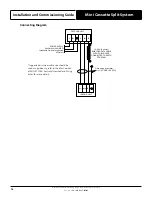
Page 18: ...OR UNIT N L POWER SUPPLY See Outdoor Unit MRC Installation Guide for suggested minimum N INDOOR UNIT N L2 Field wiring by Installer 1mm 2 CORE EARTH S S 14 0 20 0 44mm SHIELDED DATA CABLE WITH SHIELD...

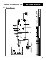
Page 19: ...MOVE JUMPER WIRE JR6 TO USE REMOTE ON OFF FUNCTION IF PROVIDED INSTALL FERRITE RING IN THE FIELD P1 CN110 S1 S TO OUTDOOR UNIT INDOOR CIRCUIT BOARD WATER LEVEL SWITCH INDOOR COIL OUTLET TEMPERATURE SE...

Page 20: ...Grille a Push both of the tabs towards the middle simultaneously to unlock the hook on the grille b Hold the grille at a 45 angle lift it up slightly and detach it from the main body 45 2 Mounting th...

Page 21: ...System Doc No 9590 5010 Ver 1 211217 3 Mount the intake grille Ensure that the buckles at the back of the grille be properly seated in the grove of the panel 4 Connect the 2 wires of the fascia panel...

Page 22: ...b Ensure the louvres move properly and can be changed using the remote control c Check to see if the room temperature is being registered correctly d Ensure the indicators on the remote control and t...

Page 23: ...ioner in COOL mode 4 Listen to the sound of the drain pump to see if it makes any unusual noises 5 Check to see that the water is discharged It may take up to one minute before the unit begins to drai...

Page 24: ...yright 2021 Actron Engineering Pty Limited ABN 34 002767240 Registered Trade Marks of Actron Engineering Pty Limited ActronAir is constantly seeking ways to improve the design of its products Therefor...

Reviews: