Installation and Commissioning Guide - Package Commercial Unit
Doc. Part No. 0525-055 Ver. 9 220308
Installation and Commissioning Guide
Package Commercial Unit
40
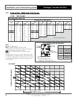
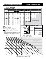
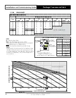
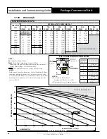
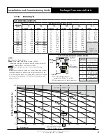
17.13. PCG400U/V/L/R
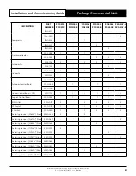
FAN PERFORMANCE DATA
AIRFLOW
(l/s)
EXTERNAL STATIC PRESSURE (Pa)
50
100
150
200
250
300
% PWM
W
% PWM
W
% PWM
W
% PWM
W
% PWM
W
% PWM
W
1750
53
909
56
1044
58
1189
62
1345
66
1487
88
1670
1800
56
981
58
1094
60
1248
65
1425
69
1566
93
1757
1850
58
1035
60
1170
64
1336
67
1504
75
1666
1900
60
1089
63
1246
67
1424
70
1582
81
1766
1950
63
1152
66
1329
70
1519
73
1685
88
1868
2000
66
1241
69
1412
72
1613
77
1788
95
1969
2050
68
1314
71
1495
75
1710
81
1892
2100
71
1423
75
1620
79
1806
86
1995
2150
74
1564
78
1721
82
1916
95
2197
MOTOR / BLOWER LIMIT
2200
77
1705
81
1821
85
2025
2250
80
1762
84
1888
89
2116
NOTES:
Performance Fan Curve shown is at Dry Coil Condition. Airflow
should be reduce with respect to the moisture content in the
air. All data provided does not include filters. Please review filter
manufacturer for application. 2.5 m/s face velocity point will
occur at 2578
l/s for PCG400U and at 2520l/s for PCG400L/R.
NOTES:
W
= Indoor Fan Power, Watts
PWM
= Pulse Width Modulation Setting, % PWM
(Adjustable through CPI3-2 Board located in electrical panel).
Factory PWM Setting = 71 % PWM for 100 Pa.
- Data in the box indicates Factory Default Setting.
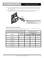
JUMPER PIN
POSITION
INDOOR FAN
A
SCG400E
PCG400U/V/L/R
B
PCG340L/R
C
PCG330U/V/L/R
D
PCG300L/R
PKA300T-L/R
E
SCG290E
PCG290U/V/L/R
F
SRG260E
PCG260U/V
(CPI3-1) COMMERCIAL PWM INTERFACE BOARD
NOTES:
LED will show PWM without %.
Example: 71% PWM = 71 in LED.
LED adjustments are in 1 digit increments.
CPI 3
23787-3
C3
DISP2 DISP1
MODEL
A
B
C
D
E
F
ADJUST
V2
C2
P3
C1
+
+
P1
P2
V1.0
U4
U3
R11
R12
R13
R14
R15
C5
D3
R3
R4
C7
R2
R1
RV1
TRA-0100-R
D1
D2
P5
TX1
240VAC OUT
INPUT
R10
C8
P6
GND
0 - 10
V
PWM1 OUT
PWM2 OUT
P4
DAMAGE DUE TO
INCORRECT WIRING
VOIDS WARRANTY
CPI3-
1
S/No:
11G1
2276
IF
ON/OFF
IF
PWR
240VAC IN
ActronAir
LED FAN
PWM
DISPLAY
JUMPER PIN
SET AS PER
TABLE BELOW
PWM
ADJUSTMENT
(POTENTIOMETER)
0
50
100
150
200
250
300
350
1750
1800
1850
1900
1950
2000
2050
2100
2150
2200
2250
Static Pressure
1750
50
150
250
350
100
200
300
0
1900
2050
1800
1950
2100
2200
1850
2000
2150
2250
90% PWM
50% PWM
55% PWM
95% PWM
MOTOR / BLOWER LIMIT
71% PWM
60% PWM
65% PWM
70% PWM
75% PWM
80% PWM
EXTERNAL S
TA
TIC PRE
SSURE (P
a)
APPLICATION RANGE
AIRFLOW (l/s)
Nominal Airflow = 2050 l/s
85% PWM


