Installation and Commissioning Guide
Package Commercial Unit
9
Installation and Commissioning Guide - Package Commercial Unit
Doc. Part No. 0525-055 Ver. 9 220308
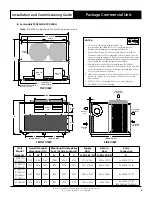
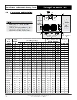
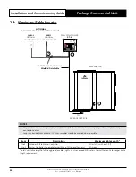
B. For models PCG233U to PCG400U
Note:
PCG400U model shown for illustration purposes only.
Unit
Model
Number
Overall Nominal
Dimension (OA)
Mounting Distance Base
Foot (Centre to Centre)
Supply
Duct
Return
Duct
Drain
Connection
H
W
L
A
B
C
H-SD x W-SD H-RD x W-RD
D
PCG233U
PCG260U
1115
1685
1265
1200
672.5
672.5
300 x 740
400 x 1200
2 x Ø 25.4 (1") ID
PCG290U
PCA300U
1330
1875
1590
1515
737.5
737.5
300 x 1065
450 x 1250
2 x Ø 25.4 (1") ID
PCA330U
PCG330U
PCA340U
PCG340U
1330
1875
1590
1515
737.5
737.5
300 x 1065
525 x 1450
2 x Ø 25.4 (1") ID
PCG400U
1315
1875
1575
1515
737.5
737.5
300 x 1065
575 x 1595
2 x Ø 25.4 (1") ID
BSP FEMALE THREAD
INDOOR COIL
INDOOR
FAN
INDOOR
FAN
OUTDOOR COIL
SUPPLY
AIR
H-RD
H-SD
C
(MTG C-C DIST)
B
(MTG C-C DIST)
H
W-SD
W-RD
50
SUPPLY
AIR
OUTDOOR
AIR INLET
OUTDOOR
AIR INLET
RETURN
AIR
A
(MTG C-C DIST)
OUTDOOR
AIR OUTLET
POWER SUPPLY ENTRY
Ø 40mm, Ø 25mm
CONDENSATE
POINTS
COMP
SIDE
CONDENSATE
DRAIN POINTS
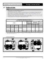
NOTES:
1. Do not scale drawing. All dimensions are
in mm unless specified. Refer to corresponding unit
dimensional drawing for mounting hole details.
2. Ensure that Service Access Areas and Spaces for Airflow
Clearances are met. This is based on the condition that the
spaces around the units are free from any obstructions and a
walkway passage of 1000mm between the units or between
the unit and the outside perimeter is available.
3. Minimum service access areas and spaces for airflow
clearances are responsibilities of the installer, ActronAir will
not be held liable for any extra charges incurred due to lack
of access and space for airflow.
4. Under all circumstances, condenser air must not recirculate
back onto condenser coil. Keep all clearance free of any
obstructions.
5. MTG C-C DIST = Mounting Centre to Centre Distance.
6. Use M12 bolt for feet mounting.
THIRD ANGLE
PROJECTION
TOP VIEW
FRONT VIEW
SIDE VIEW
D
-


