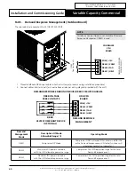
Installation and Commissioning Guide
Variable Capacity Commercial
PRELIMINARY DATA ONLY Ver. 5.01 210406
THIS LABEL TO BE REMOVED ON SIGN-OFF
27
Installation and Commissioning Guide- Package Ducted Variable Capacity Commercial
Doc. Part No. 0525-067 Ver. 5 210414
15. Configuring and Commissioning Setup
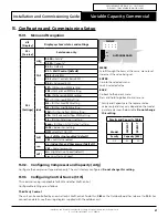
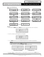
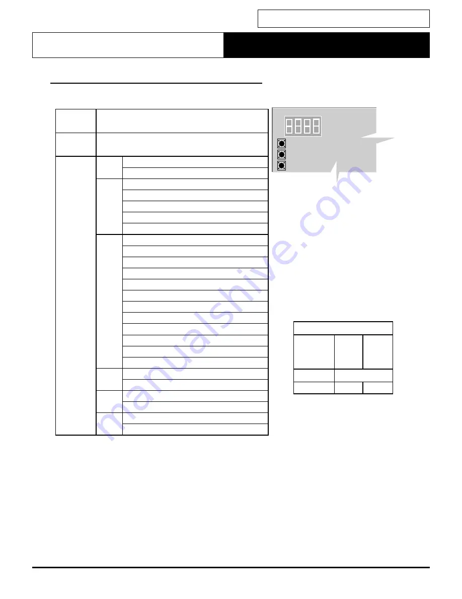
15.01. Menu and Navigation
diS
(Display)
Display system's status and settings
SEr
(Service)
Service use only
SEt
(Settings)
cnFg
02.00
= Family*
02.33
= Capacity*
CtrS
Ct.
0
= 3rd Party
Ct.
1
=
Wall Control (default)
Ct.
2
= Basic BMS
Ct.
3
= Wall C Basic BMS
Ct.
4
= Advanced BMS
iduS
FP1
= IDU Fan Low PWM setting
FP2
= IDU Fan Med PWM setting
FP3
= IDU Fan High PWM setting
Fr1
= IDU Fan Low RPM setting
Fr2
= IDU Fan Med RPM setting
Fr3
= IDU Fan High RPM setting
FPd
= IDU Fan Defrost PWM setting
FPc
= IDU Reduced Airflow PWM setting
FiL
= IDU Fan Filter Hours setting
Econ
= IDU Econ 0-10V Output setting
FnSE
= Indoor Fan Setting
HtSt
= HotStart On/Of
SoFt
no
=
Soft Start not enabled (default)
YES
= Soft Start enabled
run
no
=
Indoor Fan and Compressor (default)
YES
= Compressor only
odFs
Hi
= High Start-up Speed (default)
Lo
= Low Start-up Speed
DISPLAY
MENU
ENTER
BACK
OUTDOOR BOARD
Family and Capacity Table
Model
PKV290T
PKV3
30T
Family
Capacity (kW)
02
29
33
MENU
Scroll through the items at the same menu level.
Increment the value being set.
ENTER
Go into the selected menu.
Lock in selected value.
BACK
Go back to the parent menu.
Press and hold to go back to main menu
* Family and Capacity are the representative
values only and may vary depend on the model
purchased as seen below table .
Do not change
this setting.
15.02. Configuring Compressor and Capacity (cnFg)
Configure the compressor type and capacity. The unit is factory configured.
Do not change this setting.
15.03. Configuring Control Source (CtrS)
This commissioning is applicable for BMS and other Wall Control.
Configurable settings are as follows:
Third Party Control
The unit can be controlled by a non-ActronAir Wall Control. To do this,
CtrS
on the Outdoor Board has to be set to
Ct. 0
. For
connection details, see the wiring diagram supplied with the outdoor unit.

