Installation and Commissioning Guide
Split Ducted Outdoor Units
Installation and Commissioning Guide - Standard Commercial Split Ducted Commercial Outdoor Unit
Doc. No.0525-056
Ver. 7 220308
11
08. Banking of Units
NOTES
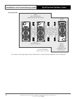
• All dimensions are in mm. Do not scale drawing.
• Ensure that Service Access Areas and Spaces for Airflow Clearances are met. This is based on the condition that the
spaces around the units are free from any obstructions and a walkway passage of 1000mm between the units or
between the unit and the outside perimeter is available.
• Minimum service access areas and spaces for airflow clearances are responsibilities of the installer, ActronAir will not be
held liable for any extra charges incurred due to lack of access and space for airflow.
• The distance between two units must be the wider clearance required.
HEIGHT CLEARANCE
FOR ALL UNITS = 1500mm
CONFIGURATION 1
*600/750 mm
AIRFLOW ALLOWANCE and SERVICE CLEARANCE - OUTDOOR COIL
NIL - TO - MINIMUM SERVICE CLEARANCE
300mm
SER
VICE CLE
AR
ANCE
800mm
SERVICE
CLEARANCE
(COMPRESSOR
AND
ELECTRICALS)
800mm
SERVICE
CLEARANCE
(COMPRESSOR
AND
ELECTRICALS)
UNIT 1
UNIT 2
*Clearances will vary depending on model. Higher capacity models clearance requirement must be allocated.
CONFIGURATION 2
UNIT 1
UNIT 2
300mm
SER
VICE
CLE
AR
ANCE
300mm
SER
VICE
CLE
AR
ANCE
NIL - TO - MINIMUM SERVICE CLEARANCE
NIL - TO - MINIMUM SERVICE CLEARANCE
800mm
SERVICE
CLEARANCE
(COMPRESSOR
AND
ELECTRICALS)
*600/750 mm AIRFLOW ALLOWANCE
AND
SERVICE CLEARANCE OUTDOOR COIL *
*600/750 mm AIRFLOW ALLOWANCE
AND
SERVICE CLEARANCE OUTDOOR COIL *
HEIGHT CLEARANCE
FOR ALL UNITS = 1500mm

