background image

Installation and Commissioning Guide - Standard Commercial Split Ducted Commercial Outdoor Unit

Doc. No.0525-056  

Ver. 7  220308

Installation and Commissioning Guide

Split Ducted Outdoor Units


6

04.  Installation Information

All service technicians handling refrigerant must be licensed to handle refrigerant gases.

Recover and Recycle Refrigerants

Never release refrigerant to the atmosphere! It is an offence in Australia to do so. Always recover, recycle and reuse 
refrigerants. When removing from the system, properly contain and identify refrigerants in its dedicated container for 
proper disposal and/or storage. Always consider the recycle or reclaim requirements of the refrigerant before beginning 
the recovery procedures. Obtain a chemical analysis of the refrigerant if necessary.  For the recovered refrigerant and 
acceptable refrigerant quality refer to the existing standards and regulations.   

Refrigerant Handling and Safety

Consult the refrigerant manufacturer’s Material Safety Data Sheet (MSDS) for information on proper handling and to 
fully understand health, safety, storage and disposal requirements. Use the approved containment vessels and refer to 
appropriate safety standards. Comply with all applicable transportation standards when shipping refrigerant containers.

Service Equipment and Recovery Procedures

Always use refrigerant reclaiming equipment in order to minimise refrigerant emissions. Use equipment and methods 
which will pull the lowest possible system vacuum while recovering and condensing refrigerant. Equipment capable of 
pulling a vacuum of less than 500 microns is required.

Do not open the system to the atmosphere for service work until refrigerant is fully removed and/or recovered.  Perform 
refrigeration system evacuation, prior to charging, in accordance with AIRAH / IRHACE Refrigerant handling code of 
practice.

Let the unit stand for 1 hour and with the vacuum not rising above 500 microns. A rise above 500 microns indicates a leak 
from the system and a leak test is required to locate and repair any leak.

 CAUTION

A leak test is always required on any repaired section of the refrigeration system.

Charge refrigerant into the system only after the equipment does not leak or contain moisture. Ensure that R-410A is 
only charged in liquid form. Take into consideration the correct amount of refrigerant charge specified for the system 
to ensure efficient unit operations. When charging is complete, reclaim refrigerant from charging lines into an approved 
refrigerant container. Seal all used refrigerant containers with approved closure devices to prevent unused refrigerant 
from escaping to the atmosphere. Take extra care to maintain all service equipment directly supporting refrigerant service 
work such as gauges, hoses, vacuum pumps and recycling equipment.

Summary of Contents for SCA260C

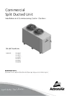
Page 1: ...on and Commissioning Guide Outdoor Model Numbers CRA300T SCA260C SCA290C SCA300C SCA330C SCA340C SCA400C IMPORTANT NOTE Please read this manual carefully before installing or operating your air condit...

Page 2: ...Operation Manual Access 7 06 Components Overview 8 07 Unit Dimensions Clearances and Weights 9 07 01 Unit Dimensions 9 07 02 Minimum Service Access Area Airflow Clearances and Weights 10 08 Banking of...

Page 3: ...omplies with the relevant council state federal codes regulations and building code standards All electrical wiring must be in accordance with current electrical authority regulations and all wiring c...

Page 4: ...h proven high quality air conditioning products Known for their durability and ActronAir is an Australian manufacturer with proven high quality air conditioning products Known for their durability and...

Page 5: ...uately supervised by a responsible person to ensure that they can use the appliance safely Young children should be supervised to ensure that they do not play with the appliance Installer must incorpo...

Page 6: ...nd Recovery Procedures Always use refrigerant reclaiming equipment in order to minimise refrigerant emissions Use equipment and methods which will pull the lowest possible system vacuum while recoveri...

Page 7: ...sure all wirings are in accordance with local electricity authority regulations and standards Do not install the unit close to an area where there is a danger of fire due to volatile explosive flammab...

Page 8: ...ways remains the ActronAir Pty Ltd Engineering Pty Ltd Copying 1 2 5 Irvine Place 4 HOLE DIAMETER 5 Modifying or Distributing without 0 5 m 0 5 m 3 FOLD 1 Norwest Business Park Bella Vista NSW 2153 GE...

Page 9: ...AS AN ADDITIONAL ACCESSORY H B A C OUTDOOR COIL COMP SIDE OUTDOOR AIR INLET AIR INLET AIR INLET AIR OUTLET W ELECT ACCESS 2 x 25 4 mm 1 GAS PIPE LIQUID PIPE SCA260 400C Gen Dim TCW SCA260 400C Gen Di...

Page 10: ...taller ActronAir will not be held liable for any extra charges incurred due to lack of access and space for airflow 4 Under all circumstances condenser air must not recirculate back onto condenser coi...

Page 11: ...ra charges incurred due to lack of access and space for airflow The distance between two units must be the wider clearance required HEIGHT CLEARANCE FOR ALL UNITS 1500mm CONFIGURATION 1 600 750 mm AIR...

Page 12: ...0mm SERVICE CLEARANCE 800mm SERVICE CLEARANCE COMPRESSOR AND ELECTRICALS 300mm SERVICE CLEARANCE 800mm SERVICE CLEARANCE COMPRESSOR AND ELECTRICALS 600 750 mm AIRFLOW ALLOWANCE and SERVICE CLEARANCE O...

Page 13: ...slings into shackle NOTE Undo the 6 screws 4 screws only for SCA260C holding down the unit unto the pallet before removing the pallet Equipment Required For Crane Lifting 1 Shackle 2 x Nylon Slings Sp...

Page 14: ...property severe personal injury or death Please check unit weight and weight distribution points as shown in the unit drawing dimensions section Procedure 1 To move the unit around with a forklift ins...

Page 15: ...WING NO MATERIAL DESCRIPTION DRAWN BY APPROVED BY SCALE DRAWN DATE FINISH F 3 intellectual property of Actron PH 61 2 8814 4000 REV 2 1 ActronAir Pty Ltd This drawing always remains the 1 HOLE DIAMETE...

Page 16: ...sing R 22 When installing equipment using R 410A refrigerant there are number of standards that must be met The compressor of this unit operates with Polyolester POE oil that rapidly absorbs moisture...

Page 17: ...0 83 0 27 0 41 Selected field pipe sizes must match the recommended sizes in Table 2 If the installation requires different field pipe diameter due to different application condition other than recomm...

Page 18: ...0 60 0 60 0 60 Max Vertical Height Differential 1 metres 20 20 20 20 20 20 20 20 20 Field Pipe Size Liquid Line inch mm 9 52 3 8 15 9 5 8 15 9 5 8 9 52 3 8 15 9 5 8 15 9 5 8 9 52 3 8 9 52 3 8 12 7 1 2...

Page 19: ...Release pressure in evaporator and remove caps 3 Fit copper tube into tail set nitro bottle and regulator up at condenser end of pipe work 4 Fit nitrogen line into liquid line with rubber bung to sea...

Page 20: ...ft in the system can cause the pressure in the high side of the system to increase and in turn the compression temperature to rise Moisture will result in adverse reaction in the refrigerant circuit T...

Page 21: ...e vacuum with dry Nitrogen to 100kPa 4 Release Nitrogen pressure Evacuate to 500 microns 5 Check vacuum with vacu stat Break the vacuum with dry Nitrogen to 100kPa 6 Release Nitrogen pressure Evacuate...

Page 22: ...ific for your air conditioning system are located on the inside of the electrical access panel Always refer all wiring installation servicing and troubleshooting of this equipment to this diagram to e...

Page 23: ...Indoor Unit Located at the back of electrical box cover OUTDOOR UNIT MAINS WIRING 400VAC Three Phase Neutral Earth 50Hz INTER CONNECTING POWER CABLE 230 VAC Single Phase Neutral Earth 50Hz 230 VAC Ac...

Page 24: ...290E 32 0 6 0 1 5 SCA300C SCA300E 32 0 6 0 1 0 SCA330C SCA330E 32 0 6 0 1 0 SCA330C SCG330E 40 0 10 0 1 5 SCA340C SCA340E 32 0 6 0 1 0 SCA340C SCG340E 40 0 10 0 1 5 SCA400C SCG400E 50 0 10 0 2 5 Sugge...

Page 25: ...0 0 44mm Shielded Data Cable must be used Total Cumulative length of all the aggregate cable lengths must not exceed 500 meters Consult ActronAir for longer cable length requirement OUTDOOR UNIT WALL...

Page 26: ...to power supply stand by for at least six hours prior to charging This is to ensure that the internal crankcase heater is operating to avoid any liquid going into the compressor that may cause damage...

Page 27: ...ture LLT _______O C Suction Line Temperature SLT ______ O C NOTES Accurate pressure and temperature measuring tools should be used to achieve satisfactory results The sensors of thermocouple must be i...

Page 28: ...e Temperature Chart record the corresponding Saturated Suction Temperature SST at the given suction pressure 2 Calculate the system super heat using the formula below Superheat SLT SST 3 If superheat...

Page 29: ...9 316 9 13 1084 7 45 2621 8 50 10 7 18 332 6 14 1119 2 46 2686 2 49 16 3 17 348 7 15 1154 6 47 2751 8 48 22 2 16 365 2 16 1190 7 48 2818 5 47 28 2 15 382 3 17 1227 5 49 2886 4 46 34 0 14 399 7 18 1265...

Page 30: ...tenance Observe proper LOCK OUT TAG OUT procedures to ensure that power cannot be inadvertently energised Failure to disconnect power before maintenance procedures can result in serious injury and or...

Page 31: ...the air inlet side of the coils Use a soft brush to remove loose dirt and debris from both sides of the coils Straighten bent coil fins with fin comb Prepare the detergent solutions according to the m...

Page 32: ...ce Methods 1 Mth 3 Mth 6 Mth 1 Yr 2 Yrs 3 Yrs 4 Yrs 5 Yrs Casing Panels and Frames Visual check for damage rust and dust accumulation For highly corrosive environment wash panels quarterly with water...

Page 33: ...Yrs Safety Devices Check calibration of safety devices such as HP and LP controls sensors etc Check resistance of sensors pressure cut in cut out of pressure controls Faults Check for any previous fau...

Page 34: ...60 440 2 2 1560 438 1 1560 463 2 1560 459 2 Crankcase Heater 2025 006 1 1 1 2025 005 2 2 2 2 Outdoor Fan 2505 130 2 2505 106 2 2 2 2 2 2505 134 2 Outdoor Control Board 2020 097 1 1 2020 045 1 1 1 1 20...

Page 35: ...CIRCUIT TEMPERATURE SETTINGS SYSTEM 1 SYSTEM 2 Supply Air Temperature o C Supply Air Temperature o C Return Air Temperature o C Return Air Temperature o C Suction Temperature o C Suction Temperature o...

Page 36: ...d Trade Marks of Actron Engineering Pty Limited ActronAir is constantly seeking ways to improve the design of its products Therefore specifications are subject to change without notice Document 0525 0...

Reviews: