Page 30
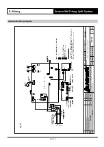
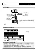
Connecting Diagram
Fig. 8.6
* Suggested minimum cable size should be used as a guide
only, refer to AS/NZS 3000 'Australia/New Zealand Wiring
Rules" for more details.
8. Wiring
Serene Wall Hung Split System
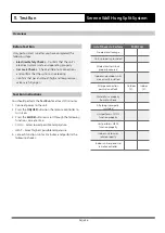
DIP Switch Settings (Indoor Board)
Fig. 8.7
SETTING NETADDRESS (CCM Com. Bus)
ENC3+F1
CODE
NETADDRESS
0-F
FACTORY
SETTING
0-15
16-31
32-47
48-63
0-F
0-F
0-F
(MULTI-FUNCTION
CONTROL BOARD)
REMOTE ON/OFF FUNCTION
F2
FACTORY
SETTING
(MULTI-FUNCTION
CONTROL BOARD)
REMOTE
SWITCH
INACTIVE
REMOTE SWITCH OPEN = UNIT ON
REMOTE SWITCH CLOSED = UNIT OFF
REMOTE SWITCH OPEN = UNIT OFF
REMOTE SWITCH CLOSED = UNIT ON
NOTE FOR REMOTE ON/OFF FUNCTION:
• Remove jumper wire in CN46 terminal and set F2 dip switch as above in the multi-function control board to use
Remote ON/OFF switch.
• When the remote switch is in "OFF" mode, the unit will be off and the remote/ wired controller will not operate.
If ON button is pressed via remote/wired controller - "CP" will be displayed.
• When the remote switch is in "ON" mode, the unit will operate via remote/wired controller as normal.
• When using remote switch, the unit will respond within 3 seconds before turning ON or OFF.
OUTDOOR UNIT
S
2(N)
N
POWER SUPPLY
(SUGGESTED MINIMUM*)
L
INDOOR UNIT
S
2(N)
1mm² INDOOR POWER
SUPPLY / DATA
(2 CORE + EARTH)
DOUBLE INSULATED
300VAC RATED MINIMUM
WRC-026AS
WRC-035AS
WRC-052AS
1.5mm² =
WRC-071AS
WRC-080AS
2.5mm² =
14/0.20 (0.44mm²)
SHIELDED DATA CABLE
WITH SHIELD WIRE
CONNECTED TO EARTH
TERMINAL
0

