background image

Page 12

Title

Low Profile Split Ducted Air Conditioner

The outdoor unit should be installed in the location that 
meets the following requirements:

þ

 Place the outdoor unit as close to the indoor unit as 

possible.

þ

 Ensure that there is enough room for installation and 

maintenance.

þ

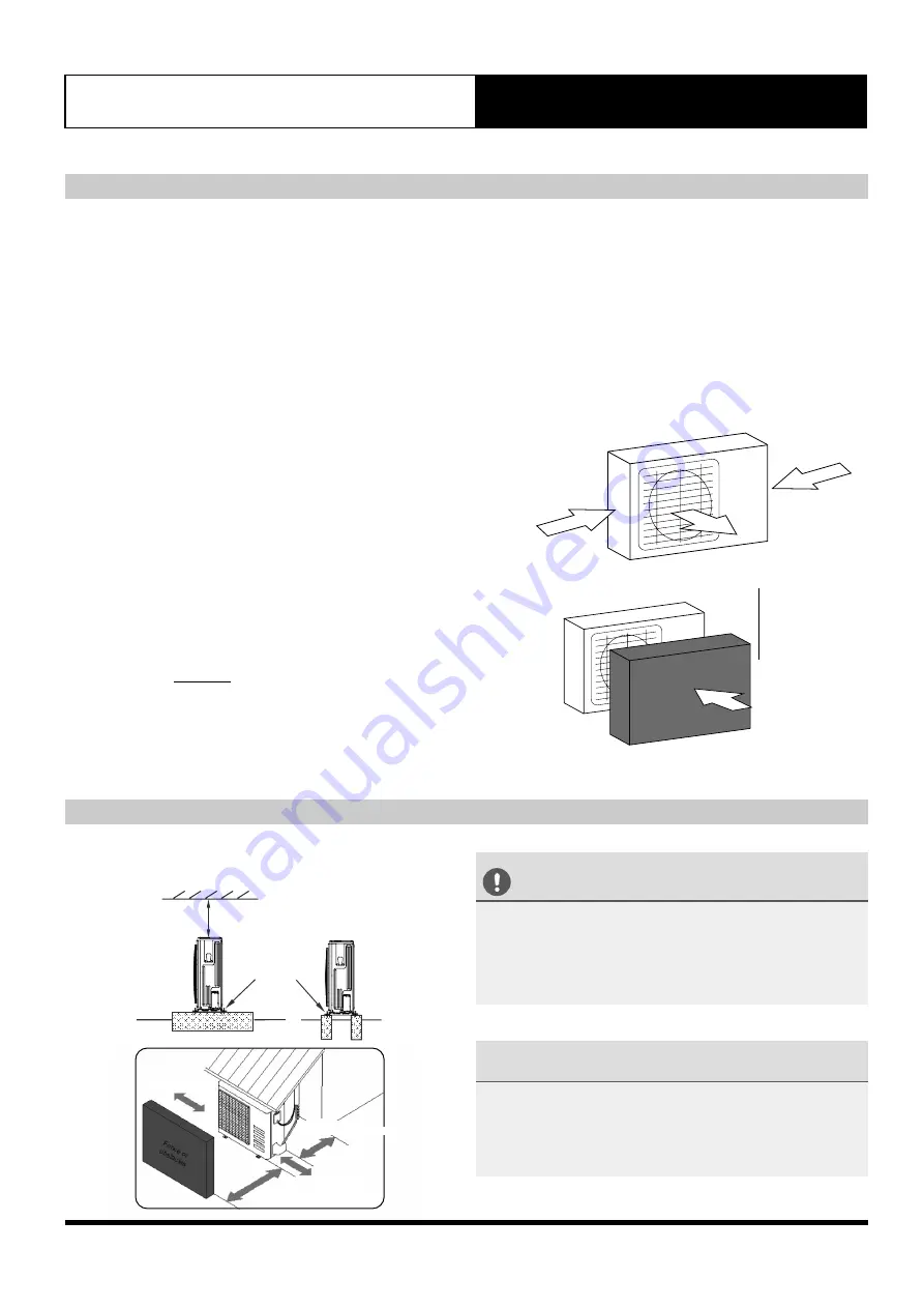
 The air inlet and outlet must not be obstructed or 

exposed to strong wind

þ

 Ensure the location of the unit will not be subject to 

snowdrifts, accumulation of leaves or other seasonal 
debris. If possible, provide an awning for the unit.      
Ensure the awning does not obstruct airflow.

þ

 The installation area must be dry and well ventilated.

þ

  There must be enough room to install the connecting 

pipes and cables and to access them for maintenance.

þ

  The area must be free of combustible gases and 

chemicals

þ

  The pipe length between the outdoor and indoor unit 

may not exceed the maximum allowable pipe length.

þ

  If possible, 

DO NOT 

install the unit where it is exposed 

to direct sunlight.

þ

  If possible, make sure the unit is located far away from 

your neighbours’ property so that the noise from the 
unit will not disturb them.

Select Installation Location

Install Outdoor Unit

Strong wind

Strong wind

Fig. 5.1

þ

  If the location is exposed to strong winds (for 

example: near a seaside), the unit must be placed 
against the wall to shelter it from the wind. If 
necessary, use an awning. Ensure minimum space 
requirements are met. (See Fig. 5.1 and 5.2)

þ

  Install the indoor and outdoor units, cables and wires 

at least 1 metre from televisions or radios to prevent 
static or image distortion. 

Fig. 5.2

Strong wind

Wind Baffle


CAUTION


•  Be sure to remove any obstacles that may block air  

    circulation.
•  Make sure you refer Fig. 5.3 to ensure there is enough 

   room for installation and maintenance.

5. Outdoor Unit Installation

Low Profile Split Ducted Air Conditioner


NOTE


The minimum distance between the outdoor unit and 
walls described in the installation guide does not apply to 
airtight rooms. 

Fix the outdoor unit with anchor bolts (M10)

>60cm


Fix with bolts 

600mm or more

150mm or more

300mm or more (LRE-170AS)

300mm or more

600mm or more

(servce access)

1200mm or more
2000mm or more (LRE-170AS)

Fig. 5.3

Summary of Contents for UltraSlim LRE-071AS

Page 1: ...ng your new air conditioning unit and keep it available for future reference That s better That s Actron Model Numbers URC 071AS LRE 071AS URC 100AS LRE 100AS URC 125AS LRE 130AS URC 140AS LRE 130AS URC 170AS LRE 170AS INSTALLATION MANUAL Low Profile Split Ducted Air Conditioner ...

Page 2: ...ypes and Specifications Notes on Drilling Hole in wall Outdoor Unit Installation 12 5 Evacuation instructions Note on adding refrigerant Drain Pipe Installation 14 6 Wiring 18 8 Page 2 Indoor Unit Parts Indoor Unit Installation Instructions Outdoor Unit wiring Indoor Unit wiring Electrical connection Test Run 29 10 Leak Test and Air Evacuation 26 9 Leak test Evacuation instructions Note on adding ...

Page 3: ...nstalled in accordance with national regulations Failure to observe a caution may result in injury or equipment damage CAUTION Note about Fluorinated Gases 1 This air conditioning unit contains fluorinated gas For specific information on the type of gas and the amount please refer to the relevant label on the unit itself 2 Installation service maintenance and repair of this unit must be performed ...

Page 4: ...is appliance is not intended for use by young children or in firm persons unless they have been adequately supervised by a responsible person to ensure that they can use the appliance safely Young children should be supervised to ensure that they do not play with the appliance 7 Installer must incorporate a means of electrical disconnection isolator in the sub mains fixed wiring in accordance with...

Page 5: ...becomes too tight you can use an additional magnetic ring in series 4c Fit magnetic ring around mains supply Refer to wiring diagrams for further shielding details S1 S2 4 Wired Controller 5 Wired Controller 1 6 Wired Controller Screws 2 Display Panel 7 Display Panel 1 Others 8 Wired Controller Manual 1 9 Owner s manual 1 10 Installation manual 1 The air conditioning system comes with the followin...

Page 6: ... Overview Low Profile Split Ducted Air Conditioner Installation Order 3 6 Install the drainpipe 1 4 2 5 Install the indoor unit Install the outdoor unit Connect the Refrigerant Pipes Leak test and evacuate the refrigeration system Connect the wires Perform a test run 7 ...

Page 7: ...ustain its weight If the structure is too weak the unit may fall causing personal injury unit and property damage or death DO NOT install the indoor unit in the bathroom or laundry room as excessive moisture can short the unit and corrode the wiring The indoor unit should be installed in the location that meets the following requirements þ There is enough room for installation and maintenance þ Th...

Page 8: ...98 LRE 130AS 1200 300 874 800 227 1044 280 1101 1240 697 LRE 170AS 1400 440 858 770 385 1188 385 1188 1436 700 Table 4 1 unit mm Dimension and Supply Air Outlet Size Return Air Inlet Size Please refer to the following data to locate the four positioning screw bolt hole on the ceiling Be sure to mark the areas where ceiling hook holes will be drilled Indoor Unit Dimensions Horizontal End H G C D A ...

Page 9: ... indoor unit You will need two people to lift and secure it Insert suspension bolts into the unit s hanging holes Fasten them using the included washers and nuts See Fig 4 8 8 Overhang the indoor unit onto the hanging crew bolts with block Position the indoor unit in a flat level by using the level indicator unless it may cause leakage See Fig 4 9 CAUTION The unit body should align perfectly with ...

Page 10: ... SP 2 40 70 pa 40 80 pa 50 90 pa 60 120 pa SP 3 70 100 pa 80 120 pa 90 140 pa 120 140 pa SP 4 100 135 pa 120 155 pa 140 195 pa 140 200 pa Set External Static Pressure Settings for external static pressure can be achieved by using the wired controller supplied with the unit When the air conditioning unit is off perform the next steps Press and hold COPY button for 3 seconds Press the button or to s...

Page 11: ...f the blower housing 3 Take off the motor Pump Maintenance 1 Screw off four screws from drain pump 2 Plug off pump power supply and water level switch cable 3 Take off pump Fig 4 14 Fig 4 13 Dimension Fig 4 12 Fresh Air Duct Installation Motor And Drain Pipe Maintenance Duct joint for fresh air Motor Blower housing Ventilated Panel Pump NOTE LRE 170AS has no duct joint ...

Page 12: ...e make sure the unit is located far away from your neighbours property so that the noise from the unit will not disturb them Select Installation Location Install Outdoor Unit Strong wind Strong wind Fig 5 1 þ If the location is exposed to strong winds for example near a seaside the unit must be placed against the wall to shelter it from the wind If necessary use an awning Ensure minimum space requ...

Page 13: ... Unit Dimensions Fig 5 4 A B D Fig 5 5 Refer to Fig 5 4 5 5 and Table 5 1 Table 5 1 unit mm Model Number Outdoor Unit Dimensions W x H x D mm Mounting Dimensions Distance A mm Distance B mm URC 071AS URC 100AS 946 x 810 x 410 673 403 URC 125AS URC 140AS URC 170AS 952 x 1333 x 415 634 404 W H ...

Page 14: ...oor Drainpipe Installation The drainpipe is used to drain water from the unit Improper installation may cause unit and property damage Indoor Drainpipe Installation Install the drainpipe as shown in Fig 6 3 1 Cover the drainpipe with heat insulation to prevent condensation and leakage 2 Attach the mouth of the drain hose to the unit s outlet pipe Sheath the mouth of the hose and clip it firmly wit...

Page 15: ... slightly sloped 75mm Indoor Drainpipe Installation continued The drain pipe installation for the unit with pump Using Drain Pump Without Drain Pump Fig 6 4 Fig 6 5 3 Using a 65 mm core drill drill a hole in the wall Make sure that the hole is drilled at a slight downward angle so that the outdoor end of the hole is lower than the indoor end by about 12mm This will ensure proper water drainage See...

Page 16: ...re the ceiling installation is completed 1 Remove the test cap and fill with about 2000ml of water into the water pan 2 Operate the air conditioner in COOL mode The sound of the drain pump shall be heard Check whether the water is discharged well 1 min lag is possible according to the length of the drain pipe and check whether there are any water leaks 3 Power off the air conditioner and replace t...

Page 17: ... shown in Table 7 1 Model Max Length of Piping Min Length of Piping Maximum Drop Height LRE 071AS 50 5 25 LRE 100AS LRE 130AS 65 5 30 LRE 170AS 65 5 30 Table 7 1 The Maximum Length and Drop Height unit mm Notes On Pipe Length and Elevation Refrigerant Piping Connection Instructions 1 Cut the connecting pipes according to required length 2 Remove burrs in the pipe Burrs can affect the air tight sea...

Page 18: ...pply terminals No other equipment should be connected to the same sub circuit as the A C unit The unit s power information can be found on the rating sticker on the product 1 Prepare the cable for connection a Ensure the correct size cable has been selected as per specification b Using wire strippers strip the rubber jacket from both ends of signal cable c Strip the insulation from the ends of the...

Page 19: ...m the ends of the internal wires c Using a wire crimper crimp fork lugs on the ends of the wires 2 Remove the cover of the electric control box on your indoor unit 3 Connect the fork lugs to the terminals Match the wire colors labels with the labels on the terminal block and firmly screw the lug of each wire to its corresponding terminal Refer to the Serial Number and Wiring Diagram located on the...

Page 20: ... JUMPER WIRE JR6 TO USE REMOTE ON OFF FUNCTION JR6 M FAN 1 CN1 IF DC INDOOR MOTOR FERRITE RING INDOOR COIL TEMPERATURE SENSOR T2 BLACK ROOM TEMPERATURE SENSOR T1 WHITE FIELD WIRING BY INSTALLER DATA CABLE MUST BE 2 CORE 14 0 20 0 44mm2 SHIELDED DATA CABLE WITH SHIELD WIRE CONNECTED TO EARTH TERMINAL ON INDOOR AND OUTDOOR FERRITE RING INSTALLER TO CONNECT IF PROVIDED 2 N FIELD WIRING BY INSTALLER F...

Page 21: ...g remains the intellectual property of Actron Engineering Pty Ltd Reproduction modification and or distribution are prohibited without written consent Revision Description B WD3010 Rev Description Date By PCR ORIGINAL A4 Size Base Model No Variation Variation Code A Drawing No Drawn Date 31 07 2017 NDL Approved Date B ReviseID and OD cable specs LC 15 03 2018 05 04 2018 WG Fig 8 3 ...

Page 22: ...RD R This drawing remains the intellectual property of Actron Engineering Pty Ltd Reproduction modification and or distribution are prohibited without written consent Revision Description B WD3011 Rev Description Date By PCR ORIGINAL A4 Size Base Model No Variation Variation Code A Drawing No Drawn Date 31 07 2017 NDL Approved Date B ReviseID and OD cable specs LC 15 03 2018 05 04 2018 WG Fig 8 4 ...

Page 23: ... BOARD CN2 CN6 U V W PFC INDUCTOR COMP 1 OF DC OUTDOOR FAN 1 DR BOARD FAN1 CN9 CN4 CN2 P6 P5 CN3 CN1 P11 P10 P9 P8 P7 P18 P17 CN22 CN35 CN8 CN9 CN10 EXV CN15 CN12 CN6 L1 L L2 N 1 L1 1 L 2 L2 1 N S1 S2 1 2 3 4 5 CN1 CN3 CON1 CN1 FAN2 FAN1 OF DC OUTDOOR FAN 2 IPM BOARD FIEL WIRING BY INSTALLER CABLE MUST BE 2 CORE 14 0 20 0 44mm2 SHIELDED DATA CABLE WITH SHIELD WIRE CONNECTED TO EARTH TERMINAL ON IN...

Page 24: ...NIMUM N INDOOR UNIT 2 N 2 5mm URC 071AS 4 0mm URC 100AS 6 0mm URC 140AS 1mm 2 CORE EARTH INDOOR UNIT CN20 S2 S1 OUTDOOR UNIT S2 2 CORE 14 0 20 0 44mm SHIELDED DATA CABLE WITH SHIELD WIRE CONNECTED TO EARTH TERMINAL Suggested minimum cable size should be used as a guide only refer to AS NZS 3000 Australia New Zealand Wiring Rules for more details URC 125AS URC 140AS URC 170AS ...

Page 25: ...IT WALL CONTROLLER INTER CONNECTING PCB CABLE INDOOR TO OUTDOOR SUB MAINS CIRCUIT BREAKER 2 DATA CABLE Supplied with the controller 12metres 4 3 MAIN SUPPLY FROM DISTRIBUTION BOARD 1 INDOOR UNIT Fig 8 6 3 EXTRA LOW VOLTAGE DATA CONTROL WIRING 2 core shielded data cable 14 0 20 0 44mm2 maximum 65 metres EXTRA LOW VOLTAGE DATA CONTROL WIRING 4 core shielded data cable 0 75mm2 maximum 12 metres 4 SUB...

Page 26: ...nsure pressure does not drop during this time To indoor unit N I T R O G E N refrigerant pipes OUTDOOR UNIT 4000 kPa leak test for 1 hour Leak Test Fig 9 1 CAUTION Use a vacuum pump and a vac stat reading lower than 500 microns and an air discharge capacity above 40L min The outdoor unit does not need vacuuming DO NOT open the outdoor unit s gas and liquid stop valves Ensure that your vac stat rea...

Page 27: ...ge Compound gauge 76cmHg Low pressure valve High pressure valve Charge hose Charge hose Vacuum pump Pressure gauge Low pressure valve OPEN VALVE STEMS GENTLY When opening valve stems turn the hexagonal wrench until it hits against the stopper DO NOT try to force the valve to open further 8 Insert hexagonal wrench into the packed valve high pressure valve and open the valve by turning the wrench in...

Page 28: ... must be opened slowly Always use protective gear when charging the system DO NOT mix refrigerant types Some systems require additional charging depending on pipe lengths The standard pipe length is 15m The additional refrigerant to be charged can be calculated using the following formula Refrigerant Charge Details Model URC 071AS LRE 071AS URC 100AS LRE 100AS URC 125AS LRE 130AS URC 140AS LRE 130...

Page 29: ... have been recorded i The power voltage is the correct voltage for the air conditioner Test Run Instructions 1 Open both the liquid and gas stop valves 2 Turn on the main power switch and allow the unit to warm up 3 Set the air conditioner to COOL mode 4 For the Indoor Unit a Ensure the wired controller operates properly b Ensure the louvres move properly and can be changed using the remote contro...

Page 30: ...ur system s proper operating performance High discharge pressures are good indication that the coils High discharge pressures are good indication that the coils need cleaning When using detergent or solvents to clean need cleaning When using detergent or solvents to clean the coils follow the manufacturer s instructions to avoid the coils follow the manufacturer s instructions to avoid potential d...

Page 31: ...uld be more than 1MΩ Heat Exchanger Check for clogging by dust Check for leaks damage Clean air inlet side as necessary Straighten any bent fins using fins comb Drain Pan Condensation line Check for obstructions free flow of water Clean to eliminate obstructions sludge check condition of pan Pour water to ensure free flow Filter Check for clogging by dust Clean Replace Filter Temperature Readings ...

Page 32: ...heck for obstructions free flow of water Clean to eliminate obstructions sludge check condition of drain line Pour water to ensure free flow Compressor Ω Check for high low pressure Measure insulation resistance Check compressor for abnormal noise vibrations Measure insulation resistance Should be more than 1MΩ Ensure to isolate first the VSD from the compressor before measuring insulation resista...

Page 33: ...Page 33 Notes Low Profile Split Ducted Air Conditioner ...

Page 34: ...Page 34 Notes Low Profile Split Ducted Air Conditioner ...

Page 35: ...Page 35 Notes Low Profile Split Ducted Air Conditioner ...

Page 36: ...actronair com au 1300 522 722 Copyright 2016 Actron Engineering Pty Limited ABN 34 002 767 240 Registered Trade Marks of Actron Engineering Pty Limited Document 9590 5002 Ver 12 Issue Date 08 2021 ...

Reviews: