Page 6
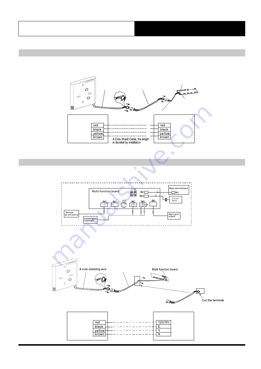
3. Wiring Connection For Wall Splits
2. Wiring Connection Diagram for Cassettes & Ducted
1. Connect wired controller to indoor unit mainboard using the connecting cables included. Connect the adaptor cable
(smaller cable) first to the indoor main board. Then connect the wired controller using the longer connecting cable.
Fig 3.2
1. Open the front panel , identify the multi function box (See Fig.3.3.1).
2. Cut the terminal of the longer connection cable (See Fig 3.3.2).
3. Connect the four wires to each of the pins in the multi function board as follows:
The red wire on wire controller connect to 12/5V pin on multi function board; black wire to E pin; yellow wire to Y pin;
brown wire to X pin. (See Fig.3.3.1).
Fig 3.3.2
Fig 3.3.1
When connecting to
4-core wired controller:
12V = Red
E = Black
Y = Yellow
X = Brown
3. Installation Method
Wired Remote Controller
Wired Controller
Multi-function board
Connecting cable
Wired Controller
Insert of the mainboard CN40
Indoor Unit
Mainboard
Connecting cable
4-core shielded cable
CN40
adaptor cable


