I – 3 T
u
rn
ing Specific Oper
ations
Datum Setting
See "Datum Setting" on page 10 for basic information. Datum settings
define the relationships between the axis positions, and the display
values. for most lathe operations there is only one X-axis datum, the
center of the chuck, but it may be helpful to define additional datums
for the Z-axis. The table can hold up to 10 datum points. The easiest
way to set datum points is to touch a workpiece at a known diameter,
or location, then enter that dimension as the value that the display
should be showing
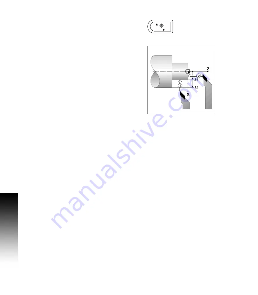
Example: Setting a workpiece datum
U
Call the tool data by selecting the tool which being used to touch the
workpiece.
U
Press the DATUM hard key. The Cursor will be in the Datum
Number field.
U
Enter the datum number, and press the DOWN ARROW key to go
to the X-axis field.
U
Touch the workpiece at point 1.
U
Enter the radius, or diameter of the workpiece at that point.
Remember to ensure the VUE is in diameter display mode (Ø) if a
diameter value is used.
U
Press the DOWN ARROW key to advance to the Z axis.
U
Touch the workpiece surface at point 2.
U
Enter the position of the tool tip (Z= 0) for the Z coordinate of the
datum.
U
Press ENTER.
Summary of Contents for VUE
Page 2: ......
Page 6: ...vi Readout Parameter Access Code ...
Page 8: ...viii VUE Fonts ...
Page 10: ...x ...
Page 14: ...xiv ...
Page 54: ...40 II 3 Dimensions ...
Page 57: ......


