POWERdrive 50W DESIGN GUIDE
–
July 30, 2020
Page 16/19
Network channel count
–
this corresponds to the number of unique DMX channels that are used; this value
should equal the highest number that is used in the Group channel mapping fields. It is important that this value
is set correctly to ensure correct RDM discovery of the driver addresses. The default value is 4.
Network resolution
–
this value defines the dimming resolution that is used; it can be either 8-bit (default),
corresponding to 256 steps, or 16-bit, corresponding to 65536 steps. Note that the 16-bit option consumes two
DMX channels which form a
“
course
”
and
“
fine
”
control of the associated output.
Network start address
–
This is the first DMX address of the driver and the default value is 1. It is typically set via
RDM during the commissioning process. All the driver channel addresses, as defined by the network channel
count and channel mapping fields, are numbered relative to the start, or base, address. For example, if all the
channels have a channel mapping value of
“
1
”
, they are all controlled by the network start address. The outputs
that are mapped to
“
2
”
would be controlled by the DMX address corresponding to the network start a 1.
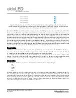
Figure 10(a) reflects the scenario where each LED output is tied to a separate DMX address (Network channel count = 4);
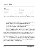
Figure 10 (b) reflects the scenario where all LED outputs are tied to a single DMX address (Network channel count = 1);
Figure 11 demonstrates how channel mapping can be used to force specific DMX addresses in situations where only a
subset of LED outputs is used. Consider a luminaire family that includes multiple luminaire configurations, each with an
ambient light and downlight component. Depending on the desired light output, the ambient light component may
require up to two LED outputs while the downlight component only requires one LED output. From an assembly
perspective, it may be desirable to always wire the downlight LED light engine to LED output 3. Figure 11 (middle) shows
the network settings that map LED output 1 and 3 to the first and third DMX address, respectively, of the POWERdrive LED
driver. In this case, the driver consumes three DMX addresses on the network. To conserve DMX addresses, though, LED
output 3 can be mapped to DMX address 2, as shown in Figure 11 (right).
(a)
(b)
Figure 10: The section DMX network settings in FluxTool gives users full control over the network settings of the driver,
including the mapping between DMX channels and LED outputs, network channel count, and network resolution.
Picture (a) reflects the scenario where each LED output is tied to a separate DMX address; picture (b) reflects the
scenario where all LED outputs are tied to a single DMX address.


