AcuBrite 15-NAV User Guide AcuBrite 15-NAV User Guide
CONNECTIONS AND CONTROL FEATURES
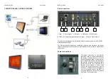
Rear connections
1.Fuse 2. Power Input 3. DVI Input 4. VGA-Input 5. RS232 Input
6. CVBS-1,2,3 Input (Composite Video ) AV Input 7.USB for Touch control
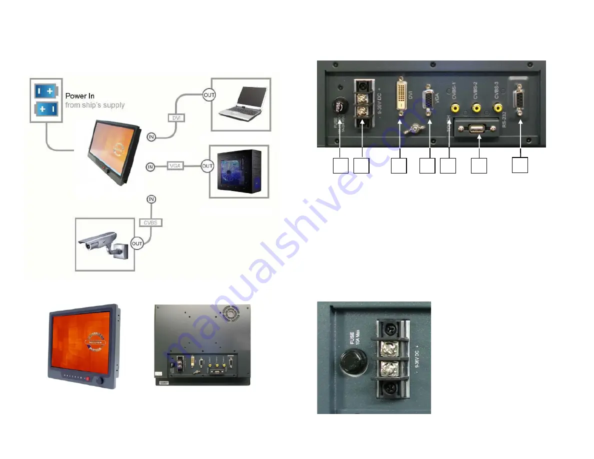
This monitor is designed to run on marine vehicle’s power systems, with 9~36V DC
wide range power input.
You must ground the monitor by connecting the drain wire (shield) of the power
input. It is important that an effective radio frequency (RF) ground is connected to
the monitor.
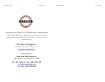
Power connections
The power connection to the monitor
should be made at either the output of
the battery. isolator switch, or at a DC
power distribution panel. AcuBrite15-Nav
recommends that power is fed directly to
the monitor via its own dedicated cable
system and MUST be protected by a
thermal circuit breaker or fuse, fitted
close to the power connection. If you do
not have a thermal circuit breaker or
fuse in your power circuit, you MUST fit
an in-line breaker or fuse to the positive
(red) lead of the power cable.
3
2
1
2
4
6
7
5
3


