background image

Chapter 4: BIOS Setup


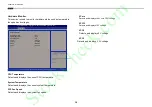
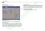
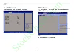
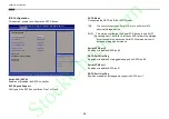
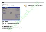
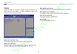
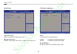
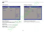
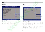
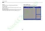
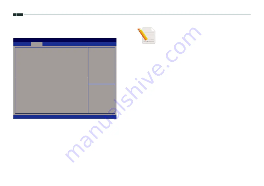
USB Configuration


This section is used to configure the USB.


Aptio Setup Utility - Copyright (C) 2013 American Megatrends, Inc.


Advanced


USB Configuration


Enables Legacy USB support.


AUTO option disables legacy


USB Module Version


8.10.27


support if no USB devices are


connected. DISABLE option will


USB Devices:


keep USB devices available


only for EFI applications.


2 Keyboards, 1 Point, 2 Hubs


Legacy USB Support


[Enabled]


USB3.0 Support


[Enabled]


XHCI Hand-off


[Enabled]


EHCI Hand-off


[Disabled]


→←: Select Screen


↑↓: Select Item


Enter: Select


+/-: Change Opt.


F1: General Help


F2: Previous Values


F3: Optimized Defaults


F4: Save & Exit


ESC: Exit


Troubleshooting: When installing Windows 7 from USB, 
USB 3.0 will not be supported. Please disable XHCI and 
enable EHCI to allow USB installation of Windows 7.


Version 2.16.1242. Copyright (C) 2013 American Megatrends, Inc.


Legacy USB Support


Enable


Enables Legacy USB.


Auto


Disables support for Legacy when no USB devices are connected.


Disable


Keeps USB devices available only for EFI applications.


USB3.0 Support


Enables or disables USB 3.0 controller support.


XHCI Hand-off and EHCI Hand-off


This is a workaround for OSs that does not support XHCI hand-off and EHCI


Hand-off. The XHCI and EHCI ownership change should be claimed by the


XHCI and EHCI driver respectively.


40


StockCheck.com

Summary of Contents for AcuPanel 12V2

Page 1: ...ura Embedded Systems Inc Rugged Panel PC Solutions Applied Panel PC AcuPanel 12V2 15V2 17V2 19V2 User Manual Acura Embedded Systems Inc www acuraembedded com Published May 2016 S t o c k C h e c k c o...

Page 2: ...uPanel12V2 12V2X 1 Specifications 2 AcuPanel15V2 4 Specifications 5 AcuPanel17V2 7 Specifications 8 AcuPanel19V2 10 Specifications 11 Knowing AcuPanel Series 13 Rear Top 13 Rear Bottom 14 Rear 15 Mech...

Page 3: ...cket 27 Panel Mounting 28 Chapter 4 BIOS Setup About BIOS Setup 30 When to Configure the BIOS 30 Default Configuration 31 Entering Setup 31 Legends 31 BIOS Setup Utility 32 Main 32 Advanced 33 Chipset...

Page 4: ...ct names mentioned herein are registered trademarks of their respective owners Regulatory Compliance Statements This section provides the FCC compliance statement for Class A devices and describes how...

Page 5: ...romium Cr6 0 1 or 1 000ppm Polybrominated biphenyls PBB 0 1 or 1 000ppm and Polybrominated diphenyl Ethers PBDE 0 1 or 1 000ppm In order to meet the RoHS compliant directives Acura Embedded Systems In...

Page 6: ...plosion if battery is incorrectly replaced Replace only with the same or equivalent type recommended by the manufacturer Discard used batteries according to the manufacturer s instructions Installatio...

Page 7: ...autions and warnings on the equipment should be noted 11 If the equipment is not used for a long time disconnect it from the power source to avoid damage by transient overvoltage 12 Never pour any liq...

Page 8: ...Handling the unit carry the unit with both hands and handle it with care 2 Maintenance to keep the unit clean use only approved cleaning products or clean with a dry cloth 3 CompactFlash Turn off the...

Page 9: ...Touch Pen 1 5 Terminal block 3 pin Phoenix Contact Plug 1 6 Flat Head for SSD Installation 4 7 Panel Mount Hole Block 12 Note Package contents may vary depending on your country region some items may...

Page 10: ...ontact Plug 1 6 Flat Head for SSD Installation 4 7 Panel Mount Hole Block 14 Note Package contents may vary depending on your country region some items may be optional Please contact your local distri...

Page 11: ...32 422 485 120SSD Brightness adjustment buttons AcuPanel15V2 15 XGA LED Backlight Touch Panel PC Intel Atom E3826 1 46GHz touch screen 2GB DDR3L 2 x RS232 422 485 120SSD Brightness adjustment buttons...

Page 12: ...Computer AcuPanel12V2X Intel Atom E3826 Dual Core Low Consumption CPU Flush Panel by 5 wire Touch Screen Dual GbE 2nd display VGA Line out PS2 KB MS USB x 3 2 x Mini PCIe sockets 1 x CFast 2 x RS232 4...

Page 13: ...DDR3L 1066 1333 Non ECC and Un buffered Storage Device 1x external locked CFast socket 1x hard drive bay optional 1x 2 5 SATA HDD or 1x SATA DOM Watchdog timer Watchdog timeout can be programmed by so...

Page 14: ...face 10 100 1000 Based Tx Ethernet compatible Mechanical Environment Color pantone black RAL 15 00 front bezel w Pantone 400C RAL 090 80 10 metal style membrane IP protection IP65 front Mounting panel...

Page 15: ...umption CPU Flush Panel by 5 wire Touch Screen Dual GbE 2nd display VGA Line out PS2 KB MS USB x 3 2 x Mini PCIe sockets 1 x CFast 2 x RS232 422 485 Fieldbus port DDR3L 2GB 2 5 HDD Bracket IP65 Compli...

Page 16: ...m temperature 25 C H W status monitor Monitoring system temperature and voltage Expansion 2x Mini PCIe sockets support optional Wi Fi 3 5G module or Fieldbus Card Rear I O Ethernet 2x RJ45 2nd display...

Page 17: ...ction IP65 front Mounting panel wall stand VESA 100mm x 100mm Power input 12V 30VDC Power adapter Optional AC to DC power adaptor 12V 60W Vibration IEC 68 2 64 w HDD 1Grms sine 5 500Hz 1hr axis HDD Op...

Page 18: ...ption CPU Flush Panel by 5 wire Touch Screen Dual GbE 2nd display VGA Line out PS2 KB MS USB x 3 2 x Mini PCIe sockets 1 x CFast 2 x RS232 422 485 Fieldbus port DDR3L 2GB 2 5 HDD Bracket IP65 Complian...

Page 19: ...m temperature 25 C H W status monitor Monitoring system temperature and voltage Expansion 2 x Mini PCIe sockets support optional Wi Fi 3 5G module or Fieldbus Card Rear I O Ethernet 2x RJ45 2nd displa...

Page 20: ...ection IP65 front Mounting panel wall stand VESA 100mm x 100mm Power input 12V 30VDC Power adapter Optional AC to DC power adaptor 12V 60W Vibration IEC 68 2 64 w HDD 1Grms sine 5 500Hz 1hr axis HDD O...

Page 21: ...umption CPU Flush Panel by 5 wire Touch Screen Dual GbE 2nd display VGA Line out PS2 KB MS USB x 3 2 x Mini PCIe sockets 1 x CFast 2 x RS232 422 485 Fieldbus port DDR3L 2GB 2 5 HDD Bracket IP65 Compli...

Page 22: ...om temperature 25 C H W status monitor Monitoring system temperature and voltage Expansion 2x Mini PCIe sockets support optional Wi Fi 3 5G module or Fieldbus Card Rear I O Ethernet 2x RJ45 2nd displa...

Page 23: ...tion IP65 front Mounting panel wall stand VESA 100mm x 100mm Power input 12V 30V DC Power adapter Optional AC to DC power adaptor 12V 60W Vibration IEC 68 2 64 w HDD 1Grms sine 5 500Hz 1hr axis HDD Op...

Page 24: ...holes are used to mount and connect optional 3 5G Wi Fi antennas CFast Card Socket Used to insert a CFast card Power Switch Press to power on or power off the panel PC Panel Backlight Control Buttons...

Page 25: ...system LAN 1 and LAN 2 Used to connect the system to a local area network LAN1 supports Wake up on LAN USB 2 0 Used to connect USB 2 0 1 1 devices USB 3 0 USB 3 0 port to connect the system with USB 3...

Page 26: ...1 Product Introduction Rear VESA Mounting Hole VESA Mounting Hole VESA Mounting Hole VESA Mounting Hole VESA Mounting Holes These are the mounting holes for VESA mount 100x100mm 15 S t o c k C h e c...

Page 27: ...sions AcuPanel12V2 12V2X 304 50 5mm 301 73 56 90 67 22 67 23 100 25 34 86 100 25 8 8 0 317 00 65 89 7 62 8 50 14 78 8 80 15 243 00 83 13 173 90 227 76 84 37 230 00 CUT OUT SIZE T 5MM MAX 108 68 100 00...

Page 28: ...duction AcuPanel15V2 371 00 5mm 366 32 160 160 00 7 41 89 26 67 22 67 23 63 20 7 8 80 19 20 CUT OUT SIZE T 5MM MAX 384 37 56 2 142 27 100 10 40 60 7 7 7 0 309 95 70 35 70 35 292 20 100 00 17 297 00 S...

Page 29: ...1 Product Introduction AcuPanel17V2 399 00 12mm 392 40 134 45 67 22 47 40 8 7 0 65 90 410 42 28 90 6 00 181 60 322 38 CUT OUT SIZE T 12MM MAX 270 00 100 00 173 90 1 0 0 0 0 18 329 00 S t o c k C h e c...

Page 30: ...00 3mm 431 34 270 36 121 32 67 22 67 23 41 49 104 50 97 35 104 50 6 9 0 457 64 61 25 24 25 8 10 16 15 10 15 52 90 76 38 379 24 111 52 174 32 361 34 111 52 366 00 CUT OUT SIZE T 3MM MAX 179 30 100 00 1...

Page 31: ...faces Line out Connector Remote Power On Off Switch Connector type 1x 3 5mm TRS Connector type 2 pin switch Connector location CN3 Connector location JP10 Pin Definition Pin Definition 1 LOUT_R 2 JD 3...

Page 32: ...n Definition Pin Definition 1 LAN1M0P 2 LAN1M0N 3 LAN1M1P 4 LAN1M2P 5 LAN1M2N 6 LAN1M1N 7 LAN1M3P 8 LAN1M3N LAN2 Port Connector type RJ45 port with LEDs Connector location LAN2 Act Status ACT LINK Fla...

Page 33: ...rt Connector type USB 3 0 port Type A Connector location CN5 1 4 5 4 1 9 5 8 Pin Definition Pin Definition 1 VCC5 2 USB 2N 3 USB 2P 4 GND 5 VCC5 6 USB 1N 7 USB 1P 8 GND Pin Definition Pin Definition 1...

Page 34: ...R COM1_RTS Reserve 7 COM1_RTS COM1_RTS Reserve 8 COM1_CTS COM1_CTS Reserve COM1_RI COM1_CTS Reserve 9 Could be a 5V Could be a 5V Could be a 5V Power Pin Power Pin Power Pin Pin RS232 RS422 RS485 1 CO...

Page 35: ...Definition Pin Definition 1 Red 2 Green 3 Blue 4 N C 5 GND 6 GND 7 GND 8 GND 9 5V 10 GND 11 N C 12 DDC Data 13 HSYNC 14 VSYNC 15 DDC Clock 12V 30V DC Power Input Connector type Phoenix Contact 1x3 3 p...

Page 36: ...GND S2 SATA_TXP2 S3 SATA_TXN2 S4 GND S5 SATA_RXN2 S6 SATA_RXP2 S7 GND PC1 CFAST_CDI PC2 GND PC3 NC PC4 NC PC5 NC PC6 NC PC7 GND PC8 CFAST_LED1_C PC9 CFAST_LED2_C PC10 NC PC11 NC PC12 NC PC13 VCC3 PC1...

Page 37: ...ssis The APPC series comes with panel mount hole blocks to cover the panel mount openings on the chassis to prevent dust invasion You can also choose to cover the panel mount holes when VESA mount is...

Page 38: ...Chapter 3 System Setup 2 Insert the hole block into the opening until it is pushed in completely 27 S t o c k C h e c k c o m...

Page 39: ...e g steel board plank acrylic board wall etc where you will mount the Panel PC must not exceed 5mm for AcuPanel12V2 12V2X 15V2 12mm for AcuPanel17V2 and 3mm for AcuPanel19V2 If the distance between th...

Page 40: ...clamps along the rear edges of the Panel PC The first and second clamps must be positioned and secured diagonally prior to mounting the rest of the clamps Tighten the clamp s screw until it touches t...

Page 41: ...MOS With easy to use pull down menus you can configure such items as Hard drives diskette drives and peripherals Video display type and display options Password protection from unauthorized use Power...

Page 42: ...curs before the display device is initialized a series of beeps will be transmitted If the error occurs after the display device is initialized the screen will display the error message Powering on th...

Page 43: ...e is based on the 24 hour military time clock For example 1 p m is 13 00 00 Hour displays hours from 00 to 23 Minute displays minutes from 00 to 59 Second displays seconds from 00 to 59 Aptio Setup Ut...

Page 44: ...Sleep State S3 Suspend to RAM Enable Hibernation Disabled Enabled Enables or Disables System ability to Hibernate OS S4 Sleep State This option may be not effective with some OS ACPI Settings IT8786E...

Page 45: ...Enter Select Change Opt F1 General Help F2 Previous Values F3 Optimized Defaults F4 Save Exit ESC Exit IT8786E Super IO Configuration Super IO Chip IT8786E Serial Port 1 Configuration Serial Port 2 Co...

Page 46: ...tor Enabled Select Screen Select Screen Select Item Select Item Enter Select Enter Select Change Opt Change Opt F1 General Help F1 General Help F2 Previous Values F2 Previous Values F3 Optimized Defau...

Page 47: ...Fan Speed N A VCore 0 828 V VCC12 11 952 V VCC5 5 040 V VCC3 3 330 V VCC5 Detects and displays 5V voltage VCC3 Detects and displays 3 3V voltage Select Screen Select Item Enter Select Change Opt F1 Ge...

Page 48: ...1460 MHz 64 bit Supported Active Processor Cores All Limit CPUID Maximum Disabled Execute Disable Bit Enabled Intel Virtualization Technology Enabled Select Screen Select Item Enter Select Change Opt...

Page 49: ...Processor Cores 2 Intel HT Technology Not Supported Intel VT x Technology Supported L1 Data Cache 24 kB x 2 L1 Code Cache 32 kB x 2 Select Screen L2 Cache 512 kB x 1 Select Item L3 Cache Not Present...

Page 50: ...Select Item Enter Select Change Opt F1 General Help F2 Previous Values F3 Optimized Defaults F4 Save Exit ESC Exit AHCI This option configures the Serial ATA drives to use AHCI Advanced Host Controlle...

Page 51: ...Help F2 Previous Values F3 Optimized Defaults F4 Save Exit ESC Exit Troubleshooting When installing Windows 7 from USB USB 3 0 will not be supported Please disable XHCI and enable EHCI to allow USB i...

Page 52: ...acklight Backlight Control Select From Tact Switch Backlight On Off Reverse Normal Backlight Dimming Reverse Normal Backlight Dimming Control By Manual Backlight Dimming Select 100 South Bridge Pyroel...

Page 53: ...lia will be unconditionally disabled Enabled Azalia will be unconditionally Enabled Auto Azalia will be enabled if present disabled otherwise Select Screen Select Item Enter Select Change Opt F1 Gener...

Page 54: ...3 Enabled Select Screen Select Screen Select Item Select Item Enter Select Enter Select Change Opt Change Opt F1 General Help F1 General Help F2 Previous Values F2 Previous Values F3 Optimized Default...

Page 55: ...SC Exit Boot Configuration Bootup NumLock State On Fast Boot Disabled Network Enabled Onboard LAN PXE Disabled Boot Option Priorities SATA PM TOSHIBA M Boot Option 1 Boot Option 2 UEFI Built in EFI Ha...

Page 56: ...t from next will be 2 and so forth Hard Drive BBS Priorities Sets the order of the legacy devices in this group Aptio Setup Utility Copyright C 2013 American Megatrends Inc Main Advanced Chipset Boot...

Page 57: ...4 Save Exit ESC Exit Version 2 16 1242 Copyright C 2013 American Megatrends Inc Save Changes and Reset To save the changes and reset select this field then press Enter A dialog box will appear Confirm...

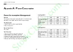
Page 58: ...1 Power up the DUT boot into Windows XP 2 Enter standby mode HDD power down 3 Measure the power consumption and record it 4 Run Burn in test program and apply 100 full loading 5 Before and after test...

Page 59: ...0 56A Total 17 52W 15 84W 16 8W Standby Mode 0 1A 0 1A 0 1A Total 1 2W 1 2W 1 2W AcuPanel12V2X 12V 24V 30V Full Loading Mode 1 45A 0 76A 0 62A Total 17 4W 18 4W 18 6W Standby Mode 0 1A 0 1A 0 1A Tota...

Reviews: