background image


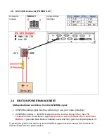
2.5    ATX 6PIN Connector (POWER OUT) 


Connector 
location 

PWROUT1 


Connector pin 
definition 

Pin 

Signal 

Pin 

Signal 

+12V 

+12V 

EXT_DI1 

GND 

GND 

EXT_DI2 


3.0    IGNITION POWER MANAGEMENT 


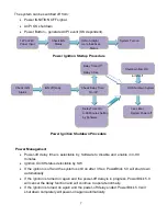
     Startup/shutdown conditions from the IGNITION signal: 


  IGNITION startup signal must be valid during 3 sec. (anti noise protection). 


  IGNITION shutdown – IGNITION signal must be inactive during 3 Sec, then PIC 

controller initiate Power Button signal (

OS must be set to shutdown from the


Power 

Button

). It generate Main Button shutdown event and then goes to


complete power off. 


Typically the system can start only from IGNITION signal, because startup PIC controller is 
disconnected from the power source. 


Summary of Contents for PowerBrick 5.0

Page 1: ...PowerBrick 5 0 User s Manual Edition 2 0 3 Generation Intel i7 Industrial Computer Acura Embedded Systems Inc...

Page 2: ...Specification 4 2 1 VGA Connector 4 2 2 GPIO Connector 4 2 3 COM Port Connector 5 2 4 Power Input Connector 5 2 5 ATX 6PIN Connector POWER OUT 6 3 0 Ignition Power Management 6 4 0 GPIO Delay Time Se...

Page 3: ...2 HD Codec onboard Watchdog Watchdog Timer Support Offer 1 255 Step Power Requirement Power Input 9V 32V DC Power input Power Protection Automatics Recovery Short Circuit Protection Power Management V...

Page 4: ...80mA Audio 1 x Line out and 1 x MIC in SIM Card Socket 2 x SIM Card sockets supported onboard with eject Environment Operating Temp 40 C 70 C Default CPU 17Watt Storage Temp 40 80 C Relative Humidity...

Page 5: ...1 2 System 3...

Page 6: ...nal Pin Signal 1 RED 2 GREEN 3 BLUE 4 NC 5 CER_DET 6 GND 7 GND 8 GND 9 5V 10 GND 11 NC 12 DAC_SDA 13 HSYNC 14 VSYNC 15 DAC_SCL 16 NC 2 2 GPIO Connector GPIO Pin Definition Pin Signal Pin Signal 1 GPI0...

Page 7: ...1 COM1 2 3 4_DCD COM1 2_RS 485_TXD RXD 2 COM1 2 3 4_RXD Com1 2_RS 485_TXD RXD 3 COM_TXD 4 COM_DTR 5 GND 6 COM_DSR 7 COM_RTS 8 COM_CTS 9 COM_RI 2 4 Power Input Connector PWRIN1 Connector definition Pin...

Page 8: ...NITION startup signal must be valid during 3 sec anti noise protection IGNITION shutdown IGNITION signal must be inactive during 3 Sec then PIC controller initiate Power Button signal OS must be set t...

Page 9: ...able in 0 99 minutes Ignition On Off status detectable by SW If the ignition is off and the system is still on after 3 Sec PowerBrick 5 0 will shut down automatically If the ignition is turned on agai...

Page 10: ...and Line O A35 A1 O A36 0F Set Bit 4 7 to Low 7 6 5 4 3 2 1 0 DO4 DO3 DO2 DO1 DI4 DI3 DI2 DI1 0 DO is low 0 DI is low 1 DO is high 1 DI is high PIO5 Output Enable Register Index A0h Bit Name R W Defau...

Page 11: ...n status 3 GPIO53_ST R 1 GPIO53 pin status 2 GPIO52_ST R 1 GPIO52 pin status 1 GPIO51_ST R 1 GPIO51 pin status 0 GPIO50_ST R 1 GPIO50 pin status GPIO5 Drive Enable Register Index A3h Bit Name R W Defa...

Page 12: ...nfiguration Port The following table describes the Control Register bit definition 7 6 5 4 3 2 1 0 0 0 1 1 Timer 0 Select output Unit pulse width of RSTOUT 0 1 sec 00 1 ms 1 60 sec 01 25 ms 10 125 ms...

Page 13: ...lect output polarity of RETOUT 1 high active 0 low active by setting the bit 1 0 WD_PSWID TH R W 0 Select output pulse width of RSTOUT 0 1 ms 1 25 ms 2 125 ms 3 5 sec Watchdog Timer Configuration Regi...

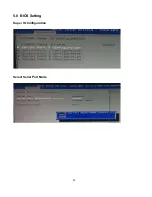
Page 14: ...5 0 BIOS Setting Super IO Configuration Select Serial Port Mode 12...

Page 15: ...ce A special customer service unit has been set up specifically to cater to our esteemed customers needs Technical Support For technical support contact your Salesperson support acuraembedded com Mail...

Reviews: