background image

Chapter 4: BIOS Setup


Chapter 4: BIOS Setup


This chapter describes how to use the BIOS setup program for the 
PowerBrick AQ6. The BIOS screens provided in this chapter are for 
reference only and may change if the BIOS is updated in the future.


About BIOS Setup


The BIOS (Basic Input and Output System) Setup program is a menu driven 
utility that enables you to make changes to the system configuration and 
tailor your system to suit your individual work needs. It is a ROM-based 
configuration utility that displays the system’s configuration status and 
provides you with a tool to set system parameters.


These parameters are stored in non-volatile battery-backed-up CMOS RAM 

that saves this information even when the power is turned off. When the 

system is turned back on, the system is configured with the values found in 

CMOS.


With easy-to-use pull down menus, you can configure such items as:


  Hard drives, diskette drives, and peripherals  


  Video display type and display options  


  Password protection from unauthorized use  


  Power management features  


The settings made in the setup program affect how the computer performs. 
It is important, therefore, first to try to understand all the setup options, and 
second, to make settings appropriate for the way you use the computer.


When to Configure the BIOS


  This program should be executed under the following conditions:  


  When changing the system configuration  


  When a configuration error is detected by the system and you are 

prompted to make changes to the setup program  


  When resetting the system clock  


  When redefining the communication ports to prevent any conflicts  


  When making changes to the Power Management configuration  


  When changing the password or making other changes to the security 

setup  


Normally, CMOS setup is needed when the system hardware is not 
consistent with the information contained in the CMOS RAM, whenever the 
CMOS RAM has lost power, or the system features need to be changed.


Summary of Contents for PowerBrick AQ6

Page 1: ...Acura Embedded Systems Inc Industrial Computing Solutions Fan less Computer PowerBrick AQ6 User Manual Acura Embedded Systems Inc www acuraembedded com Published Sept 2014...

Page 2: ...finitions 5 External I O interfaces Front Panel 5 Remote Power On Off Switch 5 COM1 Port 5 COM2 Port 5 DC Power Input 6 Chapter 3 System Setup Installing a SO DIMMl 7 Installing a CFast Card 8 Install...

Page 3: ...PU Support Onboard Intel Atom processor E3845 Quad Core 1 92 GHz Main Memory 1x DDR3L SO DIMM Socket Support DDR3L 1066 1333 4GB RAM Optional upgrade to 8GB un buffered and non ECC Display Option Dual...

Page 4: ...d Standard 7 Windows Embedded Compact 7 Linux Kernel version 3 8 0 Dimensions 185mm W x 131mm D x 54mm H without wall mount bracket Construction Aluminum and Metal Chassis with fanless design Environm...

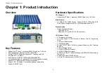
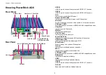
Page 5: ...a network COM1 and COM2 Two DB9 ports used to connect RS232 422 485 compatible devices CFast Slot Used to insert a CFast card SIM Slot Used to insert a SIM card 9 30V DC Input Used to plug a DC power...

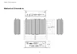
Page 6: ...Chapter 1 Product Introduction Mechanical Dimensions 25 60 94 115 131 185 194 206 54 60 4...

Page 7: ...Connector type DB 9 port 9 pin D Sub 1 2 1 5 6 9 Pin Definition 1 PBT_PU 2 GND RS232 RS485 RS422 Pin Definition Pin Definition Pin Definition 1 SP1_DCD 1 SP1_DATA 1 SP1_TX 2 SP1_RXD 2 SP1_DATA 2 SP1_T...

Page 8: ...RS485 RS422 Pin Definition Pin Definition Pin Definition Pin Definition 1 GND_FLT 2 VIN 1 SP1_DCD 1 SP1_DATA 1 SP1_TX 2 SP1_RXD 2 SP1_DATA 2 SP1_TX 3 SP1_TXD 3 NC 3 SP1_RX 4 SP1_DTR 4 NC 4 SP1_RX 5 G...

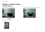
Page 9: ...tup Chapter 3 System Setup Installing a SIM Card 1 Locate the SIM card holder and release the cover 3 Close the cover and secure the holder to the original position SIM card holder 2 Place the SIM car...

Page 10: ...st slot at the front and remove the cover on the slot 2 Insert the CFast card into the slot and fasten the cover Installing a Battery 1 Locate the battery slot at the front and remove the cover on the...

Page 11: ...figure such items as Hard drives diskette drives and peripherals Video display type and display options Password protection from unauthorized use Power management features The settings made in the set...

Page 12: ...way to enter Setup is to power on the computer and wait for the following message during the POST TO ENTER SETUP BEFORE BOOT PRESS Press the key to enter Setup Scroll Bar When a scroll bar appears to...

Page 13: ...month from January to December Date displays the date from 1 to 31 Year displays the year from 1999 to 2099 System Time The time format is hour minute second The time is based on the 24 hour military...

Page 14: ...State This option may not be effective with some OS ACPI Sleep State Select the highest ACPI sleep state the system will enter when the suspend button is pressed The options are Suspend Disabled and S...

Page 15: ...port Onboard Serial Port Mode Select this to change the serial port mode to RS232 RS422 RS485 or RS485 Auto Serial Port 2 Configuration This section is used to configure serial port 2 Serial Port Ena...

Page 16: ...port Onboard Serial Port Mode Select this to change the serial port mode to RS232 RS422 RS485 or RS485 Auto Serial Port 4 Configuration This section is used to configure serial port 4 Serial Port Ena...

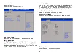
Page 17: ...CPU temperature System Temperature Detects and displays the current system temperature Fan Speed Detects and displays the fan speed VCore Detects and displays the Vcore CPU voltage VCC12 Detects and d...

Page 18: ...ur To avoid this problem enable this field to limit the return value to 3 or lesser than 3 Execute Disable Bit When this field is set to Disabled it will force the XD feature flag to always return to...

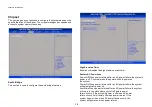
Page 19: ...arallel ATA physical storage device AHCI This option configures the Serial ATA drives to use AHCI Advanced Host Controller Interface AHCI allows the storage driver to enable the advanced Serial ATA fe...

Page 20: ...Power Off When power returns after an AC power failure the system s power is off You must press the power button to power on the system Power On When power returns after an AC power failure the system...

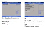
Page 21: ...13 American Megatrends Inc PCH Azalia Configuration Azalia Control detection of the Azalia device Disabled Azalia will be unconditionally disabled Enabled Azalia will be unconditionally Enabled Azalia...

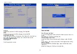
Page 22: ...sword Boot This section is used to configure the boot features Bootup NumLock State This allows you to determine the default state of the numeric keypad By default the system boots up with NumLock on...

Page 23: ...BS Priorities Boot Option 1 Sets the system boot order Save Exit Save Changes and Reset To save the changes and reset select this field then press Enter A dialog box will appear Confirm by selecting Y...

Page 24: ...dly service A special customer service unit has been set up specifically to cater to our esteemed customers needs Technical Support For technical support contact your Salesperson support acuraembedded...

Reviews: