Viewing AcuTab-M
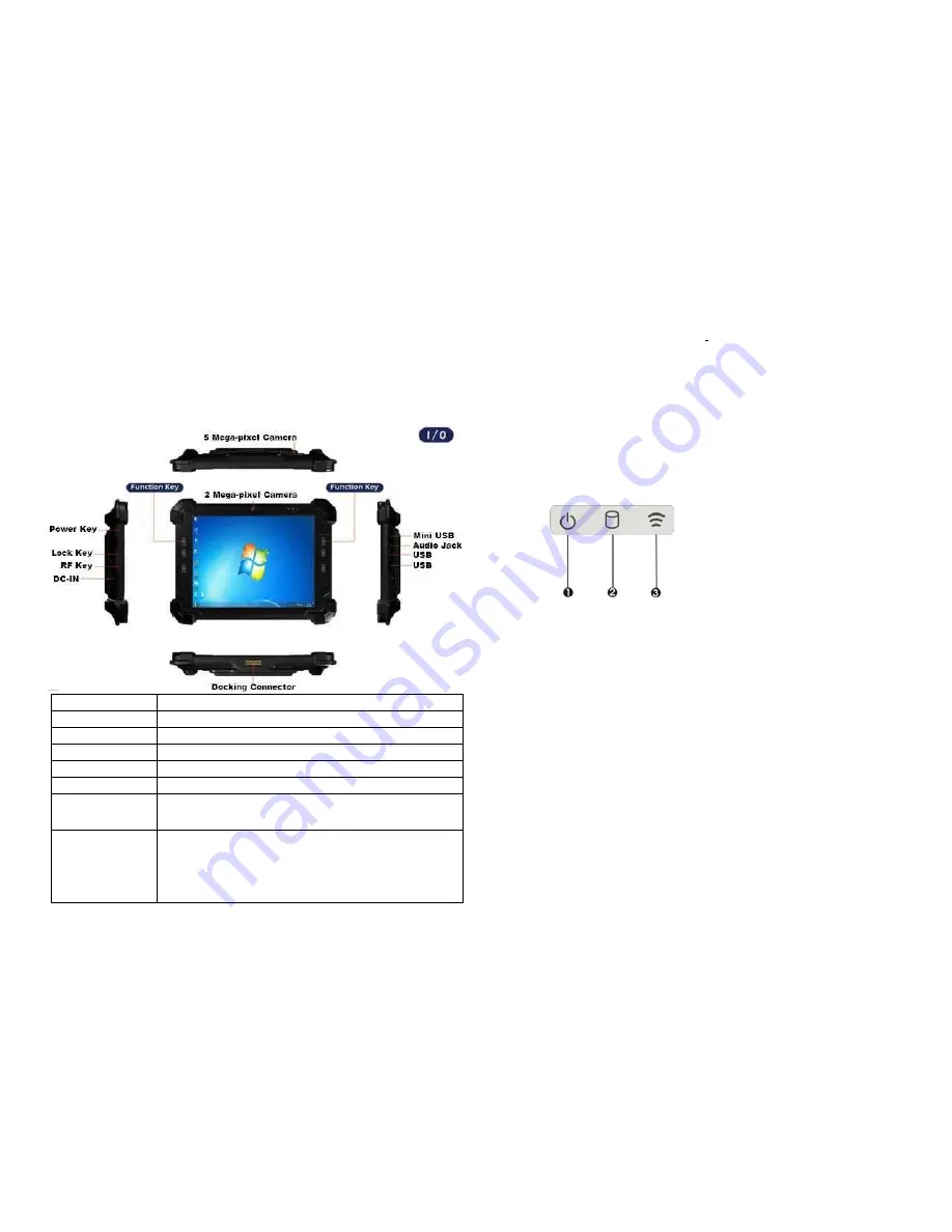
Before starting to set up the AcuTab-M, get familiar with the locations and purposes of
controls, connectors and ports, which are illustrated in the figures below. When placed
upright on the desktop, the front panel of AcuTab-M appears as shown in
below.
F1 Button
F1=explorer
F2 Button
F2=Windows Media Player
F3 Button
F3=OnScreen keyboard (osk)
F4 Button
F4=Task Manager
F5 Button
F5=Calculator
Fn Button
Fn = Hotkey Utility
Fn+F3 Button (SAS)
Implement Secure Attention Sequence (SAS)
Similar function as pressing
Ctrl-Alt-Delete
on a
standard
keyboard
Function Key
mapping during boot
(for Windows
system recovery)
F1 KEY -LEFT ARROW
F2 KEY -UP ARROW
F3 KEY -ENTER
F4 KEY -RIGHT ARROW
F5 KEY -DOWN ARROW
Camera / 2 Mega-pixel (Front-facing)
The built-in camera can be used as a communication device for allowing you to
capture images, record videos, and have video chats. It is 2M pixels and transmitting
instant image through network for conference.
Camera / 5 Mega-pixel (Rear-facing)
The built-in high resolution camera can be used as a communication device
for allowing you to capture images, record videos, and have video chats.
Power / Storage / RF wireless
Keeps you informed of your system’s current power status, storage access status,
and RF wireless devices ON/OFF status.
Power LED Indicator
Letting you know that system is turned on and indicate the battery charging
status.
•
Lights green when the system is powered on and battery is discharging
•
Lights amber when the system is powered on and battery is charging
•
Lights blinking amber when the system is in S3 sleep mode and battery
is charging or lights blinking green when the system is in S3 sleep mode
and battery is fully charged
•
Lights off when system is powered off or the battery is fully charged.
Storage Access
When LED blinking white indicates that the system is accessing the internal storage drive.
RF ON/OFF Indicator
When LED turns on, white LED indicates that a wireless device(Wifi/Bluetooth/3G/LTE) is
activated. When LED turns off, it indicates that all RF devices are being disabled.
Programmable Function Buttons (F1~F5)
These buttons is programmable to execute specific software application. When you
program the application to launch, please write this directory as listed below into the
configuration file, then the system will aware and execute this application.
1. Power LED Indicator
2. Storage Access
3. RF ON/OFF
2
3


