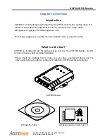
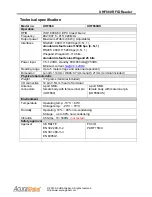
background image


UHF860 RFID Reader


© 2013 ACURA Global. All rights reserved 
http://www.acuraglobal.com 


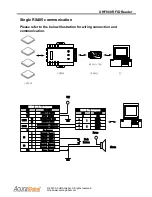
Single RS485 Installation procedure: 

The procedure is same as RS232 communication 

The difference is applying a RS485 cable to connect to PC. 


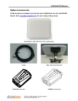
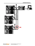
1. Apply the bundled coaxial antenna cable to connect to ANT800 with it’s N end. 


2. Then apply the other SMA end of the coaxial antenna cable to connect to one of 

UHF860’s SMA antenna ports.


3. Do not power on unless you have secured and connected the power supply to 

UHF Reader’s I/O Pins for VCC and GND communication. 


4. Connect the end of +/- at RS485 cable to UHF860’s I/O Pin for RS485+/-. 

5. Connect another end of UB485 converter cable to PC’s UBS port. 

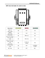
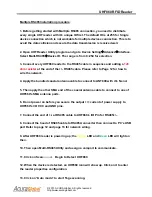
6. After UHF860 reader is powering up; the 

Yellow

 LED and 

Green

 LED will light on 

then.


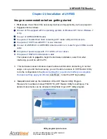
7. Next is to run the software called UHF Reader Utility to assign the available com 

port.


8. Click on “Scan” button to detect UHF860 reader 

9. 

“Device found “

 message will pop up on the screen, when the UHF860 reader is 

detected.  


10. Next click on “Auto mode” to kick off Tags reading


11. Adjust the UHF Tag to face the reading range within 5M and situate in front of 

ANT800 (Antenna).    You will see the EPC IDs displaying on UHF Reader Utility 

screen and indicates which antenna is scanning them


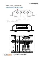
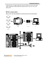
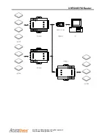
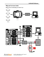
Multiple RS485 communication   

Please refer to the following illustration of connection to PC 

Summary of Contents for UHF860

Page 1: ...UHF860 RFID READER User s manual English draft April 10 2013 TM970180 Copyright 2013 ACURA Global ...

Page 2: ...itten approval from ACURA Global Inc this document is not allowed to be duplicated for the public usage The content is subjected to change without notice Revision history Version Date of issue Description 01 April 10 2013 Default ...

Page 3: ...ssories 2 Specification 3 LED reader status indication 4 Antenna port 5 I O connection 5 Chapter 2 Insatallaion of UHF860 6 Befefore getting started 6 7 RS232 interfacing 8 9 Single RS485 interfacing 10 11 Multiple RS485 interfacing 11 Wiegand interfacing 16 Chapter 3 Trouble shooting 18 ...

Page 4: ...ement Logistic of Items Management etc We strongly suggest you read this manual in details before you start the setup What s in the box UHF860 set is delivered with the basic package covering One UHF860 Reader one CD and one accessory pack as below illustration Please check the package first to make sure you have received all device and the components before you start to configure or install the U...

Page 5: ...com Optional accessories Following parts are available to purchase from ACURA Global to work with UHF860 Reader Go to sales acuraglobal com for sales inquiry of these items ANT800 EU ANT800 US Circular polarization Cable VISA Antenna bracket kit USB232BConverter USB485A Converter ...

Page 6: ...0mA 7 5VDC Minimum current 1A 7 5 12VDC Reading range Up to 5 meters tags and antenna dependent Dimension Length 114mm Width 97mm Length 21mm terminal included Physical characteristic Weight 170 grams terminal included I O connection 14 pin 3 5mm head of terminal Antenna connectors 4 port SMA female body with female inner pin UHF860 4 port SMA female body with male inner pin UHF860US Environment T...

Page 7: ... Color Yellow Power Red Tag Green Mode Power on Auto mode ON OFF ON Standby Auto mode ON OFF ON Normal read Every active ID reading ON Blink once ON Tags in sensing field communication mode ON Blink once ON Tags in sensing field Auto mode ON Continuous reading ON Communication mode ON OFF Continuous reading ISP mode ON OFF OFF ...

Page 8: ...onnection to PC VCC GND RS232 RS485 NC DI 1 2 3 4 1 2 DO GND TX RX PIN TX RX RS232 RS485 FUNCTION Transmitted Data Received Data Differential Signal Differential Signal UHF860 I O Pin Assignment Power 7 5 12VDC VCC Digital Input 1 1 Digital Input 2 2 Digital Input 3 3 Digital Input 4 4 Digital Output 1 1 Digital Output 2 2 DI DO Power Ground GND Power Ground GND No Connect NC ...

Page 9: ...e One piece of power supply with 7 5 12VDC at 1A or above One piece of RS232 Communication cable Then please refer to page 8 to begin the hardware installation select first what interfacing you will do with the PC 3 This hardware manual introduces basic hardware information and setting in normal usage once you did the basic setup you will be able to access to UHF Reader Utility to do the configura...

Page 10: ...HF Reader Utility with the Basic Setting value The output value could be different depending on the features of other brand antennas or UHF tags you are applying with ANT800 antenna is the optional device to work with UHF860 developed by ACURA You are able to do the further complete configuration in advanced setting to meet your on site applications go further to UHF utility ...

Page 11: ...RS232 to USB PC USB232B UHF860 Push Button PIN 2 3 4 5 FUNCTION Received Data Transmitted Data Data Terminal Ready Signal Ground RS232 Pin Assignment Data Carrier Detect 1 PIN TX RX RS232 RS485 FUNCTION Transmitted Data Received Data Differential Signal Differential Signal UHF860 I O Pin Assignment Power 7 5 12VDC VCC Digital Input 1 1 Digital Input 2 2 Digital Input 3 3 Digital Input 4 4 Digital ...

Page 12: ...232 connector with it s cable to PC com port If the PC is not equipped with the RS232 port the alternative way is applying a RS232 USB converter to communicate with PC USB port 6 After UHF860 reader is powering up the Yellow LED and Green LED will light on then 7 Next is to run the software called UHF Reader Utility and assign the available com port 8 Click on Scan button to detect the UHF860 read...

Page 13: ...C USB485A Push Button PIN 1 2 FUNCTION RS485 RS485 RS485 RS485 USB485 Pin Assignment GND G PIN TX RX RS232 RS485 FUNCTION Transmitted Data Received Data Differential Signal Differential Signal UHF860 I O Pin Assignment Power 7 5 12VDC VCC Digital Input 1 1 Digital Input 2 2 Digital Input 3 3 Digital Input 4 4 Digital Output 1 1 Digital Output 2 2 DI DO Power Ground GND Power Ground GND No Connect ...

Page 14: ...RS485 cable to UHF860 s I O Pin for RS485 5 Connect another end of UB485 converter cable to PC s UBS port 6 After UHF860 reader is powering up the Yellow LED and Green LED will light on then 7 Next is to run the software called UHF Reader Utility to assign the available com port 8 Click on Scan button to detect UHF860 reader 9 Device found message will pop up on the screen when the UHF860 reader i...

Page 15: ...UHF860 RFID Reader 2013 ACURA Global All rights reserved http www acuraglobal com ANT800 UHF860 RS485 to USB PC USB485A ANT800 UHF860 ANT800 UHF860 ...

Page 16: ...Connect NC VCC PIN TX RX RS232 RS485 FUNCTION Transmitted Data Received Data Differential Signal Differential Signal UHF860 I O Pin Assignment Power 7 5 12VDC VCC Digital Input 1 1 Digital Input 2 2 Digital Input 3 3 Digital Input 4 4 Digital Output 1 1 Digital Output 2 2 DI DO Power Ground GND Power Ground GND No Connect NC VCC PIN TX RX RS232 RS485 FUNCTION Transmitted Data Received Data Differe...

Page 17: ... cable Please refer to Page 12 for how to wire the network 4 Apply the bundled coaxial antenna cable to connect to ANT800 with it s N end 5 Then apply the other SMA end of the coaxial antenna cable to connect to one of UHF860 s SMA antenna ports 6 Do not power on before you secure the output current of power supply to UHF860 s I O VCC and GND pins 7 Connect the end of at RS485 cable to UHF860 s I ...

Page 18: ...ghts reserved http www acuraglobal com 14 Adjust the UHF Tag to face the reading range within 5M and situate in front of ANT800 Antenna You will see the EPC IDs displaying on UHF Reader Utility screen and indicates which antenna is scanning them ...

Page 19: ...al Signal UHF860 I O Pin Assignment Power 7 5 12VDC VCC Digital Input1 1 Digital Input2 2 Digital Input 3 3 Digital Input4 4 Digital Output1 1 Digital Output2 2 DI DO Power Ground GND Power Ground GND No Connect NC VCC 5V Pull high 220ohm Wiegand Interface Control Borad D0 D1 D0 D1 PIN 2 3 4 5 FUNCTION Received Data Transmitted Data Data Terminal Ready Signal Ground RS232 Pin Assignment Data Carri...

Page 20: ...you are connecting to a Wiegand interface controller then connect UHF680 I O pins of DO1 DO2 to the controller s Do D1 port we suggest to add a Pullhigh resister on D0 D1 wire as illustration on page 15 7 After UHF860 reader is powering up the Yellow LED and Green LED will light on 8 Then open Multi RS485 Utility and assign a comport to communicate 9 Click on Scan Begin to Detect UHF860 10 When th...

Page 21: ...ight e tag and comply to ISO18000 Class 1 Gen 2 5 Move the tag closer to the antenna Q3 How to do when the distance is too short or tags are in hassle conditions Answer 1 Please check if there is the other UHF reader with the same frequency nearby 2 Please check if there is any large electronic equipment working around 3 Make sure that there is no obstacle between the antenna and the tag 4 Please ...

Reviews: