1
WaterMaster®
25 (X) - 35 - 45 (X) - 70 (X) - 85 Evo
WaterMaster®
120 Evo
36
A1009341-664Y8300 • B
STARTING UP THE APPLIANCE
Set-up conditions
•
All connections made
•
Gas conversion carried out as required
•
Condensate trap full of water
•
Electrical power supply on
•
Gas supply open
•
Hydraulic circuit(s) full of water
Procedure
1. Check that there is no gas leak.
2. Depress the ON/OFF master switch ( ).
3. Check the gas pressure and allow the appliance to heat up
for a few minutes
4. Check and adjust the burner according to local standards
and regulations, refer to the procedure on the right.
5. Set the Domestic Hot Water temperature to the required
value using the control panel. Refer to
and to the Installer’s Handbook.
6. After 5 minutes of operation, bleed the primary circuit until
all air is evacuated and restore a 1.5 bar pressure.
7. If required, top it up with water to get the required pressure.
Follow-on tasks
1. Close the primary circuit filling valve and disconnect the fill-
ing connection as required.
2. Check that there are no leaks.
3. Check that the flow rate in the appliance is sufficient as
follows :
•
Operate the appliance at maximum power
•
Once the temperatures are stable, read out the supply
and return temperatures
•
Check that the difference between the supply and re-
turn temperature is equal or less than 20k.
•
If the Delta T is higher than 20k, check the pump set-
tings/specifications.
CHECKING AND ADJUSTING THE
BURNER
When the burner operates at full power, the
CO
2
rate must be within the limits mentioned in
the technical characteristics, (see
Set-up conditions
•
Front top panel and top panel removed. See ML Booklet.
•
Operating appliance
Procedure
1. Check if the ACVMAX parameters are set to meet the us-
er's requirements (refer to
), and change them if required.
2. Put the appliance to maximum power mode (Refer to the
Installer’s Handbook).
3. Using a pressure tester, check that the dynamic gas pres-
sure at the gas valve is at least 18 mbar.
4. Allow the appliance to heat for a few minutes until it reach-
es at least 60°C.
5. Measure the burner combustion by placing the flue gas
analyzer probe in the measurement unit port on the flue
pipe and compare the CO and CO
2
values displayed with
those indicated in the combustion characteristics table.
6. If the CO
2
value differs by more than 0.3% (WM 25 (X) to
85 Evo) or 0.2% (WM 120 Evo), carry out the adjustment
mentioned in the procedure below.
7. Then put the appliance to the minimum power mode
(Refer to the Installer's Handbook). Allow the appliance to
stabilize for a few minutes.
8. Measure the burner combustion and compare the CO
and CO
2
values displayed with those indicated in the
combustion characteristics table.
9. If the CO
2
value differs by more than 0.3% (WM 25 to 85
Evo) or 0.2% (HWM 120 Evo), contact ACV’s customer’s
support.
CO
2
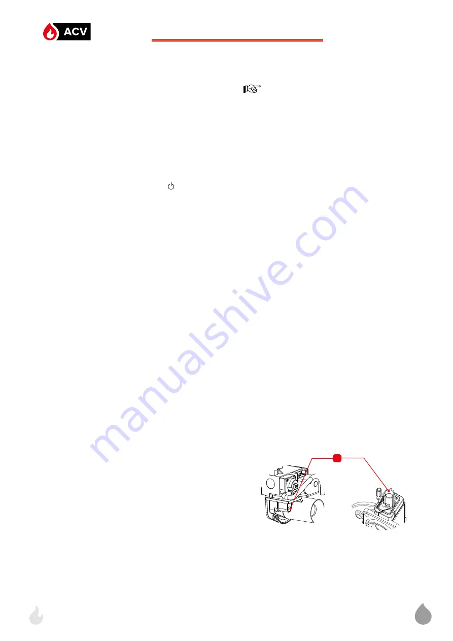
Adjustment Procedure
To adjust the CO
2
rate, rotate the throttle screw (
1
) in small steps :
on the WM 25 (X) to 85 :
•
to the left (counterclockwise)
to increase the
CO
2
rate.
•
to the right (clockwise)
to decrease the
CO
2
rate.
On the WM 120 :
•
to the right (clockwise)
to increase the
CO
2
rate.
•
to the left (counterclockwise)
to decrease the
CO
2
rate.
Follow-on tasks
Reinstall all removed access panels. See
ML booklet
EN
Commissioning
Summary of Contents for WaterMaster 120 Evo
Page 48: ...ACV International Oude Vijverweg 6 B 1653 Dworp Belgium belgium service acv com www acv com...
Page 49: ...A1009341_664Y8300 B WaterMaster 25 35 45 70 85 120 Evo 25 45 70 X Evo ML...
Page 57: ...9 x4 x4 x4 1 2 x2 ML...
Page 59: ...11 x7 WM 25 35 45 Evo x9 WM25X 45X 70 85 120Evo x11 WM 70 X Evo x3 x2 ML...
Page 60: ...12 WaterMaster 70 X Evo x4 ML...
Page 61: ...13 6 3 2 1 x4 x4 WaterMaster 25 X 35 45 X 70 85 120 Evo ML...
Page 75: ...31 ML...
Page 76: ...ACV International Oude Vijverweg 6 B 1653 Dworp Belgium belgium service acv com www acv com...


