3.1 OPERATIONAL PROBLEMS
PROBLEM
Pump won’t
prime
Pump hums but
will not operate
Low capacity
Pump runs
slowly
Motor stalls
Motor overheats
Motor will not
turn on
Fluid leakage
POSSIBLE CAUSE
1. Suction line problem
2. Bypass valve open
3. Vanes sticking
4. Gasket leakage
5. Excessive rotor or
vane wear
6. Outlet blocked
1. Dirt in pump cavity
2. Motor failure
3. Broken key
1. Excessive dirt in
screen
2. Suction line problem
3. Bypass valve sticking
4. Vanes sticking
5. Excessive rotor or
vane wear
6. Hose or nozzle
damage
7. Plugged filter
8. Low fluid level
1. Incorrect voltage
2. Vanes sticking
3. Wiring problem
4. Motor problem
1. Bypass valve sticking
2. Low voltage
3. Excessive rotor or
vane wear
4. Debris in pump cavity
1. Pumping high
viscosity fluids
2. Clogged screen
3. Restricted suction
pipe
4. Motor failure
5. Pump rotor lock-up
1. No power
2. Switch failure
3. Motor failure
4. Thermal protector
failure
5. Incorrect/loose wiring
1. Bad o-ring gasket
2. Dirty shaft seal
3. Bad shaft seal
4. Incompatible fluid
5. Loose fasteners
SOLUTION
Check for leaks in suction line
Remove and inspect valve; must
move freely & free of debris
Check vanes and slots for nicks,
burrs and wear
Tighten covers and joints
Check rotor and vanes for exces-
sive wear or damage
Check pump outlet, hose, nozzle
and filter for blockage
Clean out pump cavity
Return to place of purchase
Remove all debris & replace key
Remove and clean screen
Check suction line for leaks or
restrictions; it may be too small,
too long or not airtight
Remove and inspect valve
Check vanes and slots for wear
Check rotor and vanes for exces-
sive wear or damage
Replace hose or nozzle
Replace filter
Fill tank
Check incoming line voltage while
pump is running
Check vanes and slots for wear
Check for loose connections
Return to place of purchase
Remove and inspect valve
Check incoming voltage while
pump is running
Check rotor and vanes for exces-
sive wear
Clean pump cavity
These fluids can only be pumped
for short periods of time
(less than 30 minutes duty cycle)
Remove and clean screen
Remove and clean pipe
Return to place of purchase
Clean and check pump rotor, vanes
Check incoming power
Return to place of purchase
Return to place of purchase
Return to place of purchase
Check wiring
Check all o-ring gaskets
Clean seal and seal cavity
Replace seal
Refer wetted parts list to fluid
manufacturer
Tighten fasteners
PA1 60 • PA2 80-100 L • LIGHTPUMP 60-80-100 L • DRUM TECH 60-80-100 L • HI-TECH 60-80-100 L •
ADAM PUMPS
3
1.3 TRANSPORT AND UNPACKING
Due to its weight and dimensions, the unit can easily be moved
by hand. Inspect the package for damage and verify that the
unit is not damaged. Damage must be reported within 10 days
of receiving the unit.
For correct unpacking carefully follow these instructions:
1. Placed the case on the ground following the indications on the
package.
2. Carefully open the case, remove the unit and place it on the ground
or on a steady surface.
3. Verify that the pump and its accessories are not damaged. Remove
the plugs in the pump inlet and in the flow meter outlet.
4. Fasten the panel, placing unit on the ground or on a steady surface
in an environment with a temperature between -20° C and +50° C.
The area should be well lit and ventilated. The unit should be placed
as near as possible to the level of liquid to be pumped (maximum
height of 2 m above the liquid level).
5. Screw the delivery hose onto the flange of the flowmeter and into
the filling nozzle.
6. We suggest to use a ADAM PUMPSsuction hose; or use a diesel
resistant rubber or plastic suction hose, spiral shaped, with
a 25 mm internal diameter. The hose must be liquid tight. If a
4 meter or longer hose is used, we suggest to use a foot valve
with pressure relief and screen. We suggest using a ADAM PUMPS
hose and ADAM PUMPS(nozzle to obtain optimal performance and
safety.
2. USE AND STARTING
2.1 ELECTRICAL POWER CONNECTION (220 V)
The pump must be provided with a safety device of 30mA mini-
mum Din standard. The plug must be connected to an earthed
SHUKO socket. Do not cut or replace the provided plug.
2.2 STARTING
Once the plumbing is properly installed, the electrical cable is
connected and the filling nozzle is in the closed position, the
pump is ready to be used.
After placing the suction hose into the tank and the nozzle into
the filling hole, turn on the electrical power switch to the pump,
gradually release the nozzle lever to start diesel transfer. Once
the filling is done, close the filling nozzle and turn off the electri-
cal power switch.
The pump should be disconnected from power source when not
in use.
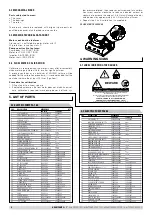
WARNINGS
1. Do not leave the nozzle unattended to avoid
oil overflow. Do not operate the pump without liquid. Do
not start the pump before connecting suction and deli-
very hoses.
2. Once the nozzle is closed, switch the pump off as soon
as possible.
3. In case of power loss, the pump should be switched off
and the plug disconnected to avoid unexpected starts.
4. Do not use the pump with wet hands, barefoot, or while
standing in water.
5. This machine has a 30 minutes duty cycle. If it is used
for a longer period, the temperature could raise above
60 °C.
3. MAINTENANCE
All maintenance or repair should always be carried out when the
machine is stopped, the power source is disconnected, and the
equipment has been emptied of fluid.
For a better operation, every three months inspect and clean the
flow meter screen.
Summary of Contents for PA1 60
Page 2: ...NOTE...


