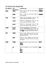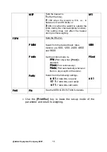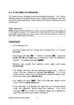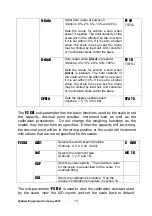
settings. This is useful if it is not possible to have a good calibration of a
scale. It will show the load cell is causing the A/D to increment correctly
through the complete range of weights needed and you can recall the
default settings for the scale. The “
trl
” value can be modified to cause
the scale calibration to change to a known amount without the need for
putting weights on the scale.
trl
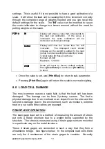
Display will show a value that corresponds to
the load cell calibration. If the value is
increased the scale calibration will be
decreased a similar percentage.
CoUnt
Display will show the counts from the A/D
converter. The displayed count should
increase as the weight is added to the load
cell up to and exceeding the capacity of scale.
Typical range for these counts are:
No load 20,000
Maximum 120,000
P3 Pro
rESEt
Scale will reset to factory default settings.
Press
[Zero/Enter]
to continue or
[Print/Esc]
to abort.
•
Once the value is set, use
[Print/Esc]
to return to sub-parameter.
•
Pressing
[Print/Esc]
again will return the scale to normal weighing.
8.0 LOAD CELL DAMAGE
The most common reason a scale fails is that the load cell has been
damaged. The damage can be from 2 primary causes. The first is
physical damage due to an overload or an impact from the side and the
second is damage due to the environment, such as moisture, extreme
heat or a cut cable if the cables are exposed.
PRINCIPLE OF OPERATION
The stain gage load cell is a method of measuring the amount of stress
put onto a metal structure due to a weight being supported by the
structure. The stress is measured using 4 strain gage sensors mounted
in a particular way on the metal structure.
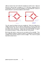
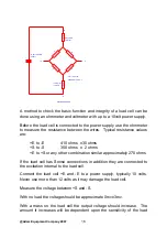
These 4 strain gages are connected in such a way that they form a
wheatstone bridge. See figure below. In the simplest load cells there
are only the 4 resistances of the strain gages to consider. Normally
@Adam Equipment Company 2007
14


