background image

Summary of Contents for ACO Series

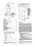
Page 1: ...equivalent JrJllR ti G l mproper installation adjustment alteration service or maintenance can cause injury or property damage Refer to this manual For assistance or additional information consult a l...

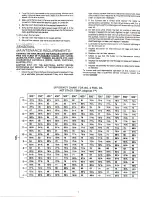
Page 2: ...wilh utmost care and will give years of trouble tree service when properly installed These instructions are intended for lhe use of qualilied individuals specifically trained and experienced In the I...

Page 3: ...nirols 3 A furnac installed in a garage must be located so that the burner and ignition source are located al least 18 lnches above the floor and the furnace must be protecled lo prevent physical dama...

Page 4: ...l warm air runs should have dampers i anced room by room Dampers minimum o 2o and a maximum I sletic pressure in the warm air plenum The temperature risg ln the f urnace must also be c hecked and the...

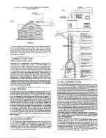
Page 5: ...verhave less lhan 100 square inchss of freearea Refer to NFPA 31 fol more detailed inlormation See figure A and B i i Eji i f G i at a z All fuel piping must be in conformance with local codes or in l...

Page 6: ...ding The omoke reading must never exceed I trace and the CO should be minimum of 90 6 O maximum of 8 s 4 Record the net stack lemperature net actual flue gas temperature minm lhe room air temperature...

Page 7: ...7 Check to see lhat lhe fluiter on lhe barometric control swings lreely B lnspect the flue pipe for rust through or scale and replace il needed 9 Inspect lhe chimney for obslructions or delects ano re...

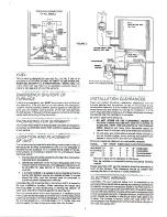
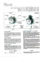
Page 8: ...and could result in loss ol prime 1 l 1 13 1 f a a DISEONNECT POVJ R SUFPLV BEFGRE UXIRING 7O PRW NT E ECTRICfTL SHOGK OR eO JlPlfrENT BJI IIAGE Lead wires on these devices are long nough to r ech th...

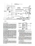
Page 9: ...CAPACITY GPH AT t00 Psl RPIJ l1v B2V E200 31Y eU BlY rqIr 3 t16 345t tn il ll liank is above pump change to Finings valves and lilters will roducc lobl longlh allowod ALL INSTALIITIONS SHOULD BE MADE...

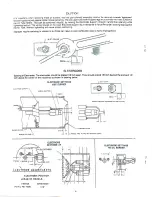
Page 10: ...rFonE Spacing of Electrodes The electrodes should be spaced 1 8 inch aparl They should exlend 1 8 Inch beyond the end and 112 inch above the cenler ol the nozzle lip as shown in drawing below EL RODE...

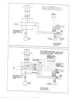
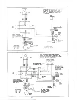
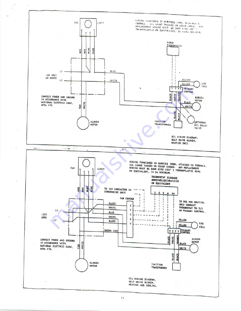
Page 11: ...ER IDATING ONLT HrRlltc futNlSttED lN HAnNtSr LL LE DS _ T cGro o iiii6 ioigl ill lii lhlfl 1x I _l rusr tr DoNE Nrrr ta ok Equrv LENr ri d iiiiriii c THEllroPLAstrc HtRr TltElIostA surrAsE rclrrrrlus...

Page 12: ...t DtlvD ll otEt Ht4Tlltc oxLY LIHI UII1NC URNTSIIED IN IIARTIESS TONH ATTACHED IO FUNilACE ALL LEADS TAGGE D OT COLOI CODDD ANY REPLACETEN IIIiIIIG IIUST DE DOIi VIfl tO5 C THERXO PLISTIC OR EQUIVAIEN...

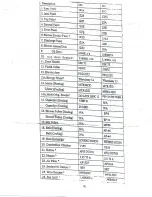
Page 13: ...Di l25A 27f I 26A 9 Door ail 2 2t606V2 216061 zc 1t c r75 i 5 12 sh Collar 3 350Fc 13 Blo Asry 121 sy 12 4DD r T L I t2 PB121sMTRBK l OMFD 20 BP8 line E MF58 4 40 6 Ee q g Bclt t9 so230 vt50 50 D0702...

Page 14: ...r Piroel rowcr Dividcrpaoel s I 26A 9 Door 06t 2 2t606V2 Ci 1 Docr DasRet 216061 2c 11 c l 5 12 sh Collar 23 35oFc 13 Bl Assy 121 l2l assy 12 4DD t2 PB121sMTRBK lFD 20 BP8 BP MF58 SO23o Yt50 50 rr __...

Reviews: