background image

3-14

Adaptec CI/O Management Software User’s Guide

3

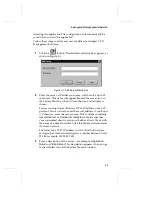
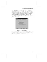
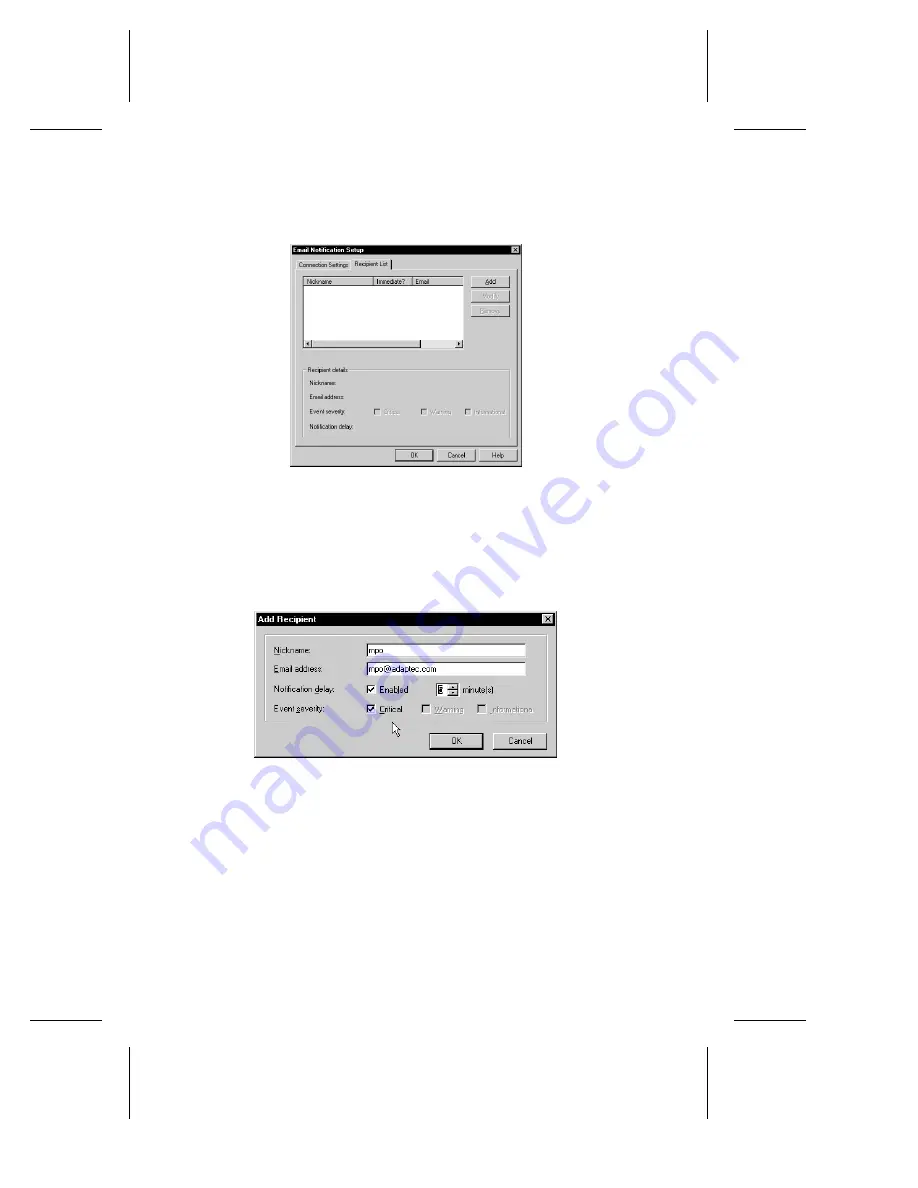
Click on the Recipient List tab to display the Recipient dialog 
box as shown in Figure 3-7.  

4

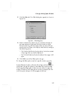
In this dialog box you can add, modify, or remove recipients. If 
you select Add, the Add Recipient dialog box will appear as 
shown in Figure Figure 3-8. 

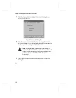
5

Enter the following information in the Add Recipient dialog 
box. 

Nickname:

 Enter an alias for the email recipient. 

Email address:

 Enter the recipient’s email address.

Figure 3-7. Recipient List Dialog Box

Figure 3-8. Add Recipient Dialog Box

Summary of Contents for 133U2

Page 1: ...USER S GUIDE ADAPTEC CI O MANAGEMENT SOFTWARE ...

Page 2: ...as Boulevard Milpitas CA 95035 R 1999 Adaptec Inc All rights reserved Adaptec and the Adaptec logo are trademarks of Adaptec Inc which may be regis tered in some jurisdictions Printed in Singapore STOCK NO 512061 00 Rev B MO 2 99 ...

Page 3: ...R AdaptecCI O Management Software User s Guide ...

Page 4: ...ithout notification to its users Adaptec Technical Support and Services If you have questions about installing or using your Adaptec product check this user s guide first you will find answers to most of your questions here If you need further assistance please contact us We offer the following support and information services Electronic Support Technical information including product literature a...

Page 5: ...ked Windows 95 98 or NT Client 12 Installing the TIRPC Communications Module on NetWare Servers v4 11 and v 5 0 18 Installing the Adaptec CI O Management Software on Novell NetWare Servers 19 Installing Adaptec CI O Management Software on UnixWare 7 0 x Servers 21 Mount the CD ROM for UnixWare v7 0 x 21 Install the Adaptec CI O Management Software on UnixWare v7 0 x 22 Uninstalling the Adaptec CI ...

Page 6: ...Viewing SCSI Devices 4 2 Viewing the SCSI Information Dialog Box 4 4 Viewing SCSI Adapter and Array Controller Information 4 6 Viewing SCSI Channel Information 4 8 Rescanning the SCSI Adapters and Array Controllers 4 9 Differences in Rescan Between SCSI Adapters and Array Controllers 4 9 Rescan Details 4 9 Managing SCSI Adapters 4 10 5 Configuring Arrays and Spares Creating an Array 5 2 Making an ...

Page 7: ... line Array 7 8 Changing an Array Name 7 8 Forcing a Spare 7 9 Performing Spare Operations 7 10 Testing All Spares 7 10 Blinking the Spare Drive Light 7 11 Performing Disk Operations 7 12 Blinking the Drive Light 7 12 Downing the Drive 7 13 Pausing I O to an Array Disk Drive 7 13 8 Scheduling and Monitoring Array Operations Setting Scheduling Options 8 2 Viewing and Managing Scheduled Activities 8...

Page 8: ...rite Caching 10 12 Other Performance Tips 10 13 Selecting a RAID Level for an Array 10 14 A Configuration Settings I O Manager Settings A 2 B SAF TE Enclosure Management Viewing Enclosure Information B 2 Viewing Subsystem Status Details B 4 Temperature Sensors B 4 Fans B 5 Power Supplies B 5 Identification of Events B 6 Events for SAF TE Enclosures B 6 Events for Devices Connected to RAID Boards B...

Page 9: ...e Adaptec CI O Management Software to perform the following operations Install and use Adaptec CI O Management Software View SCSI devices Create arrays and perform array spare and disk operations Replace drives Overview of Adaptec CI O Management Software 1 2 Conventions 1 3 ...

Page 10: ...or servers running under different operating systems Set up regularly scheduled verification of fault tolerant arrays and testing of spares We recommend that you respond immediately to arrays in Critical status by promptly replacing a failed disk using a spare Use Adaptec CI O Management Software running either on the local console or on a networked client to add delete or reconfigure arrays after...

Page 11: ...ages Save changes and for text that must be typed exactly as shown Helvetica Italics Used for program and file names when referenced in the text these changes are made to the config sys file This document includes three kinds of advisories Note Notes are reminders tips or suggestions that might simplify the procedures included in this document Caution Cautions alert you to actions that might cause...

Page 12: ......

Page 13: ...g Adaptec CI O Management Software on a Networked Windows 95 98 or NT Client 2 12 Installing the TIRPC Communications Module on NetWare Servers v4 11 and v 5 0 2 18 Installing the Adaptec CI O Management Software on Novell NetWare Servers 2 19 Installing Adaptec CI O Management Software on UnixWare 7 0 x Servers 2 21 Mount the CD ROM for UnixWare v7 0 x 2 21 Install the Adaptec CI O Management Sof...

Page 14: ...chapter describes how to install Adaptec CI O Management Software on the following Windows 95 98 or NT client Windows NT server or workstation Novell NetWare server UnixWare server It also describes how to install the TIRPC Communications Module on NetWare ...

Page 15: ...Windows NT 2 Insert the Adaptec CI O Management Software CD ROM in your CD ROM drive 3 Locate the Adaptec CI O Management Software Setup Appli cation Double click on the My Computer icon Double click on the CD ROM drive icon Click on Cio400 then click on WINDOWS_95_NT Click on disk 1 4 Double click the Setup Application icon The Welcome screen appears as shown in Figure Figure 2 1 Figure 2 1 Welco...

Page 16: ...n appears 6 If you are setting up a Windows NT server select Networked System and click on Next If you are setting up a stand alone Windows NT Workstation select Stand alone system and click on Next The Information screen appears Figure 2 2 Setup Type Selection Screen Figure 2 3 Information Screen ...

Page 17: ...he Browse button to select the pathname for your installa tion folder or select the default path Click on Next The Select Components screen appears Note If you are using a Stand alone system choice B the Select Components Screen Figure 2 5 will not appear Figure 2 4 Choose Destination Location Screen ...

Page 18: ...ser s Guide 9 Select the components you want to install and clear the compo nents you do not want to install Click on Next The Select Pro gram Folder screen appears Figure 2 5 Select Components Screen Figure 2 6 Select Program Folder Screen ...

Page 19: ...rs If you previously selected Stand alone system choice B in the Steup Type Selection 2 2 screen the Compo nents Selected will list only IO Manager Service and Console User Interface 11 Click on Next to begin copying files When the files are copied the CI O ReadMe file appears as shown in Figure 2 8 Figure 2 7 Start Copying Files Screen Figure 2 8 CI O ReadMe file ...

Page 20: ...up is now complete Select Yes I want to restart my computer now Click on Finish 14 Wait while the system reboots Note The NT services for Adaptec CI O Management Software are configured to start automatically at boot time After installation you can start or stop these services through the Services icon in the Windows NT Control Panel Figure 2 9 Setup Complete Screen ...

Page 21: ...ftware The default case sensitive password is adaptec See Chapter 9 Setting Security Options for information on setting security options Stopping CI O Array Management Service 4 00 Follow these steps to stop the CI O Array Management services in Windows NT 1 Double click the My Computer icon 2 Double click the Control Panel icon 3 Double click the Services icon as shown in Figure 2 10 4 Highlight ...

Page 22: ...ftware User s Guide 5 Repeat step 4 to stop NobleNet Portmapper Modifying Automatic Start of the Services 1 Double click the My Computer icon 2 Double click the Control Panel icon 3 Double click the Services icon Figure 2 11 Services ...

Page 23: ...rRPC Command CIOArrayManagerRPC Event and NobleNet Portmapper Uninstalling the Adaptec CI O Management Software in Windows Follow these steps to uninstall the Adaptec CI O Management Software in Windows 1 Double click the My Computer icon 2 Double click the Control Panel icon 3 Double click the Add Remove Programs icon 4 Select Adaptec CI O Management Software 4 00 and click Add Remove Follow the ...

Page 24: ...you If you select Networked System A in the Setup Type Selection screen you do not need to setup the NT client again Note Before you start the Adaptec CI O Management Software be sure that communication with the server via the network is already established As long as communication is established you do not need to log on to the server to monitor the I O subsystem of that system via the network Se...

Page 25: ...Double click on the My Computer icon and then double click on the CD ROM drive icon Click on Cio400 and then click on WINDOWS_95_NT Click on disk 1 4 Double click on the Setup icon The Welcome screen appears Figure 2 13 Welcome Screen ...

Page 26: ...nder Windows NT the Setup Type Selection screen appears This window does not appear if you are running under Windows 95 98 6 Select Networked client user interface only and click on Next The Information screen appears Figure 2 14 Setup Type Selection Screen Figure 2 15 Information Screen ...

Page 27: ...Location screen appears 8 Use the Browse button to select the pathname for your installa tion folder or select the default path Click on Next The Select Program Folders screen appears Figure 2 16 Choose Destination Location Screen Figure 2 17 Select Program Folder Screen ...

Page 28: ...ting folders list or type a new folder name Click on Next The Start Copying Files screen appears 10 Click on Next to begin copying files Once the folders are cop ied the CI O ReadMe file appears as shown in Figure Figure 2 19 Figure 2 18 Start Copying Files Screen Figure 2 19 CI O ReadMe file ...

Page 29: ...art the user interface for Adaptec CI O Management Soft ware go to Start Programs Adaptec CI O Management Software Click the icon Note You must have the proper level of Adaptec CI O Management Software password authorization if you want to add and delete arrays and spares The default case sensitive password is adaptec See Chapter 9 Setting Security Options for information on setting security optio...

Page 30: ...nstallation Options for NW4 11 from the Configurations Options menu 5 Select Install a Product Not Listed from the Other Installation Actions menu 6 Press F3 key to specify your path 7 Enter the path to the CD ROM for example d The CD ROM drive must be a DOS CD ROM drive For more details refer to the Installation and Hardware Guide for your product 8 Select Continue and access the CD ROM from the ...

Page 31: ...tions module is installed see the following section Also ensure that communication with the server via the network is already established See the documentation provided with your TCP IP software for instructions on establishing communications For communications supported over TCP IP the following steps must be completed The tcpip nlm must be loaded and the IP protocol must be bound to a valid IP a...

Page 32: ...t cio400 netware nwsetup nlm on the CD ROM 4 From the NWSETUP Select Operation menu select Default Installation or Custom Installation press F1 for help 5 At the Install menu press Enter 6 If the message File SYS SYSTEM nwaspi cdm already exists displays select overwrite 7 At the end of the installation process press Enter when you are prompted to update the autoexec ncf file This adds the appropr...

Page 33: ...ations Mount the CD ROM for UnixWare v7 0 x 1 Log onto UnixWare as a desktop user and open the SCO Administration Utility 2 Double click on the File system Manager to open it 3 At the Filesystem Manager select Mount Add Mount Configuration Local 4 At the Local Mount Configuration window Go to the Mount Point box and enter the mount point pathname Go to the When to Mount box and select Now Go to Ad...

Page 34: ...oint for the CD ROM 5 Click on the CIO400 directory and then click on UnixWare Use the arrow keys to highlight the cio40 directory and then click Select 6 At the Application Installer Window the cio40 icon appears Click on Install to begin the installation process 7 Next you need to remove the mount configuration Locate the Filesystem Manager screen and select the correct CD ROM mount point pathna...

Page 35: ...O Management Software on UnixWare v7 0 x 1 In the System Administration window double click on Software Management 2 Double click on Application Installer 3 In the Application Installer window click on the cio40 directory 4 Click on the Remove button to start the uninstall process 5 You must manually remove the ciodata directory from your system ...

Page 36: ......

Page 37: ...ng System Information 3 5 Reconnecting to a Server 3 6 Deleting a Server Address 3 7 Viewing a List of Current System Events 3 7 Entering and Viewing Preference Information 3 10 Changing Filter Options 3 10 Selecting Notification Settings 3 12 Viewing Historical Information 3 15 Interpreting and Responding to Event Messages 3 17 Additional Preference Information 3 18 ...

Page 38: ...lled and that communications have been established between the system and the networked clients or other consoles 1 Start Windows 2 Double click the icon in the Adaptec CI O Management Software group to start the program Note You can choose how you want to launch the Adaptec CI O Management Software by using the Launch tab in the Preferences Dialog box You can start the application in maximized mo...

Page 39: ...under Windows NT and NetWare use an IP protocol You can always enter the server address if you know it Otherwise enter the server name This could be something like mainserver or mainserver unisystem com Be sure that your networked client is set up with either a hosts file or with the name of a domain resolver Ask the System Administrator if you are not sure The format of a TCP IP address is nnn nn...

Page 40: ...error This means that you entered a server address with correct IP syntax but there is no server with this address Check your typing for errors and try again Transport not present This means that the TCP IP protocol transport is not present on your system Duplicate server exists This means that you entered a server name or address that has already been added for this networked client monitoring li...

Page 41: ...he Adaptec CI O Management Software will automatically attempt to reattach to the server within a user selectable time The default is 10 minutes See Additional Preference Information on page 3 18 to learn how to change the default Click the Reconnect button to immediately attempt a reconnect If you still cannot reconnect try closing the Adaptec CI O Management Software and restarting it System has...

Page 42: ...ion about system icons Reconnecting to a Server If a server has lost connection you may need to use the Reconnect command to re establish server communication To do this 1 Click to open the System Monitor window 2 Highlight the server you need to reconnect 3 Click on the System Monitor window toolbar Note If you are running Adaptec CI O Management Software from a networked client and the message G...

Page 43: ... server 3 At the prompt click Yes to confirm the deletion of the currently selected server Viewing a List of Current System Events When you run Adaptec CI O Management Software you can use the System Monitor window to monitor events on all systems to which you are connected Event notifications can be sorted according to date time name severity or description starting from the time you begin monito...

Page 44: ...nts occur and a date and time is listed for each event A green bullet to the left of an event indicates that the event has not been viewed yet To specify how the events are ordered click on the column heading you wish to sort by See Interpreting and Responding to Event Messages on page 3 17 for more information on how to respond to these messages Note The client sorts events from different systems...

Page 45: ... Close when you are finished viewing the Event Detail dialog box When you do this you automatically notify Adaptec CI O Management Software that you have read the event notification To mark all new event notifications from all systems without reading each individually click the button on the System Monitor window toolbar This stops the Adaptec CI O Management Software icon from flashing when the a...

Page 46: ...indow when you are finished viewing the events or leave it open so you are aware of events as they occur Entering and Viewing Preference Information You use the Preferences dialog box to enter or view information about how event notifications are handled and to enable and configure password protection for servers and networked clients Changing Filter Options You can control what kinds of event ent...

Page 47: ... below the log entries counts the number of messages that are actually displayed The Total field indicates the total number of messages of all types 4 Click OK to record the Filter option changes To change the filter options only for a specific window open the System Monitor window or Historic Event Log and click on the toolbar Change the options as described above and click OK The changed setting...

Page 48: ...alog box 2 Click the Notification tab the Notification dialog box appears as shown in Figure 3 5 3 Select or deselect the check boxes to control how you will be notified of event notifications received from all systems to which Adaptec CI O Management Software is connected For non critical events the flashing will occur only when the application does not have the focus Note Regardless of the optio...

Page 49: ...nnection non modem or a Dial up connection modem To enable the Dial up connection your system must have Windows Dial Up Networking DUN installed If you select a Dial up connection modem you must enter a User Name and the correct password in the Dial Up Entry Properties box In the Dial Up Entry Setup box select a dial up entry from the list Click the Create New button if you want to create a new en...

Page 50: ... you can add modify or remove recipients If you select Add the Add Recipient dialog box will appear as shown in Figure Figure 3 8 5 Enter the following information in the Add Recipient dialog box Nickname Enter an alias for the email recipient Email address Enter the recipient s email address Figure 3 7 Recipient List Dialog Box Figure 3 8 Add Recipient Dialog Box ...

Page 51: ... event severity notices you must check the Email checkbox in the Preferences Event Notification dialog box see Figure Figure 3 5 The Email box must be checked for both non critical and critical event severity types 6 Click OK Viewing Historical Information Use the Historic Event Log to view historical information for any system to which you are connected If you are running the console version of t...

Page 52: ...he column heading by which you wish to sort A color coded circle at the beginning of each message indicates its severity See the next section Interpreting and Responding to Event Messages for more information 3 To view detailed information about an entry on the list double click the entry The Event Detail dialog box appears as shown in Figure 3 3 on page 3 9 4 Click Close when you are finished vie...

Page 53: ...to Event Messages Server events can have three different severity levels as described in the following table Symbol Severity Level Description Red dot Critical Indicates an array or system problem requiring immediate action For example an array going off line because two array members have failed See Responding to a Critical Array on page 10 2 for more information Yellow dot Warning Indicates an a...

Page 54: ...nt client will verify continued access to all monitored servers and check for any missed events We recommend a value of 10 minutes Note If you are using a workstation this panel is not necessary and will not be provided Additionally this panel is not available if you are directly monitoring a local system without accessing it through the network 3 Click the Notification tab to change the way in wh...

Page 55: ... select all the boxes so you are fully informed of server events The Filter Dialog box appears as shown in Figure 3 4 on page 3 11 5 Click the Password tab to display the Password dialog box as shown in Figure 3 11 6 Select a Password Time out option to set the level of password protection for this workstation or server See Setting Security Options on page 9 1 for more information Figure 3 11 Pass...

Page 56: ...t Adaptec CI O Management Software in maximized mode or you can set it up as a status bar icon Note We recommend configuring your system to automatically start CI O as a status bar icon after each reboot That ensures that you will be notified of any problems that your RAID or SCSI subsystem encounter 9 Click OK to change the option information or to close the dialog box Figure 3 12 Launch Dialog B...

Page 57: ...I Information Dialog Box 4 4 Viewing SCSI Adapter and Array Controller Information 4 6 Viewing SCSI Channel Information 4 8 Rescanning the SCSI Adapters and Array Controllers 4 9 Differences in Rescan Between SCSI Adapters and Array Controllers 4 9 Rescan Details 4 9 Managing SCSI Adapters 4 10 ...

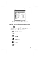
Page 58: ...indow in the Configuration View The Physical Resources window contains the Graphical View as shown in Figure 4 1 and the Detailed View as shown in Figure 4 2 The Detailed view provides more detail about a SCSI device and includes Utilization Status and Capacity information Click to open the Storage Configuration window Figure 4 1 Physical Resources Window Graphical View Array Controller SCSI Adapt...

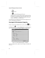
Page 59: ...pter or controller 1 Click to open the Storage Configuration window 2 Right click the icon of the device and select Information from the drop down menu The icons are as follows Controller or Adapter Channel Disk Drive CD ROM Drive Tape Drive Scanner Figure 4 2 Physical Resources Window Detailed View ...

Page 60: ... a SCSI drive or a CD ROM drive The following sections explain the information that appears for the device in the Information dialog box Viewing the SCSI Information Dialog Box When you right click a SCSI Device icon such as a disk or a CD ROM drive and select Information from the drop down menu the SCSI Information dialog box appears as shown in 4 4 Figure 4 3 displays the Description tab while F...

Page 61: ...eing used for RAID a RAID Usage group box displays If the device has single usage a string appears with the text Member of R9 or Pool Spare If the device has multiple usage a listbox appears listing all of the usages The following information appears in the Information Dialog box Status tab Overall Current status of the device for example OK Down Failed spare Reconstructing or Target of Reconstruc...

Page 62: ... Tab Figure 4 5 displays the Description tab while Figure 4 6 displays the Capabilities tab Click the Description tab for the status number of channels and size of the installed cache of the selected controller The index field contains a reference to a particular adapter The Context area in this menu displays information such as the system type host bus type and bus number The PCI bus number field...

Page 63: ...uct and the contents of the list may be different for SCSI and RAID products You cannot enable or disable the capabilities on the list it is for reference only If the adapter has a battery a Battery page will be included in the Controller Information dialog box Click Close to close the Controller Information dialog box Figure 4 6 Controller Information Dialog Box Capabilities Tab ...

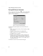
Page 64: ...atus of the channel for example Active Inactive Channel The type of channel for example SCSI System the name of the system containing the channel Controller the type of controller Devices number of SCSI devices currently connected to the channel current and the maximum number of SCSI devices that the channel supports The channel itself is counted in this maximum number If this number is 16 for exa...

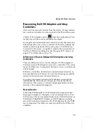
Page 65: ...he Adaptec CI O Management Software rescans SCSI adapters versus array controllers This is due mainly to differences in complexity between an array controller and a SCSI adapter With array controllers information is stored in reserved sectors on the array disk drives When rescan is selected the program quickly retrieves information from the reserved sectors In contrast information related to SCSI ...

Page 66: ... possible device failures Adaptec CI O Management Software performs three distinct tasks for SCSI adapters Discovery Poll and Statistics The time the software takes to detect system changes is directly affected by how the Discovery Poll cycles respond Devices that are new or recovered are detected at the next Discovery cycle whereas devices that have failed are detected at either the next Poll or ...

Page 67: ...known to be present By default the software runs the Poll phase every 3 minutes which can be modified in the iomgr ini file on the system During this phase the Adaptec CI O Management Software performs the following steps Verifies that the number of host adapters is the same as in the Discovery phase Performs a host adapter inquiry on each host adapter that already appears in the internal tables t...

Page 68: ...Software User s Guide During this phase the following are performed Iterates through all host adapters and devices Gathers statistics for each host adapter or device This data is currently only available from SNMP or DMI interfaces ...

Page 69: ...oftware You must know the Adaptec CI O Management Software password to add and delete arrays and spares See Chapter 9 Setting Security Options for more information Creating an Array 5 2 Making an Array the First Virtual Device 5 9 Deleting an Array 5 10 Initializing an Array 5 11 Creating Dedicated Spares or a Spare Pool 5 14 Deleting a Spare 5 17 ...

Page 70: ...ware Note When you create an array using different capacity drives the smallest capacity drive used will determine the actual member size 1 Click to open the Storage Configuration window All array and spare configuration tasks are done from within this view You can select a Graphical view as shown in Figure 5 1 or a Detailed view as shown in Figure 5 2 ...

Page 71: ...on the right side represent the system s logical resources the arrays and spares you define 2 Before you start defining the new array decide what RAID level you want to use how many disks you want it to have and whether you want to define dedicated spares spares that can be used only by this array See Selecting a RAID Level for an Array on page 10 14 Figure 5 1 Configuration Graphical View Figure ...

Page 72: ...elected disk has a partition and whether the partition is visible to the operating system To use a disk with a recognized partition in the array exit from Adaptec CI O Management Software back up any data you want to keep and delete the partition from the disk Caution All data on a disk is deleted when it becomes an array member Back up any data you want to keep before selecting a disk as an array...

Page 73: ...pares You cannot use devices attached to SCSI adapters as array members or spares 5 Select disks for the new array by highlighting the disk in the Available drives window and clicking Add The disk moves to the New member drives window and the Allowable RAID types windows changes to reflect allowable RAID levels given the current number of disks selected Do not include disks that you want to use as...

Page 74: ...rs including spaces and any other printable characters 8 Highlight the desired RAID type for the array in the Select array type window The bar graphs on the right show the relative levels of data protection read performance write performance and capacity utilization for each RAID type Note Only valid RAID configurations that are possible using the specified number of disks in the new array are dis...

Page 75: ...city of the spare Note We recommend using a spare pool instead of dedicated spares See Creating Dedicated Spares or a Spare Pool on page 5 14 for more information Spares in a spare pool can be used by any suitable array on the controller 11 Select Cache Enabled to enable cache for the array If the cache enabled checkbox is greyed out this means that no cache is available If caching is available bu...

Page 76: ...re you can write data to them We recommend that you zero initialize RAID 0 arrays as well 15 Select the desired stripe size from the Stripe size drop down list 16 Click Finish The array will be initialized at this point unless you deselected auto initialize If you deselected auto initialize skip to Step 18 To abort the initialization process not recommended open the Activity View window select the...

Page 77: ...stand alone disk To use a stand alone SCSI disk as your boot device we recommend that you assign SCSI ID 0 to this device and that you connect it to Channel A of the array controller You make an array bootable by assigning it virtual device order 0 The virtual device order is the sequence in which the system s operating system detects the arrays single disks and other devices connected to the arra...

Page 78: ...ore information 7 Make sure that you restart CI O after you reboot the server The next time you boot the system it will attempt to use this array as the boot device Deleting an Array Caution Back up the data on an array before you delete it All data on the array disks is lost when you delete the array If you delete an array all the disks that were part of the array become single stand alone disks ...

Page 79: ...Software again and delete the array 4 When the confirmation message appears confirm that you want to delete the array Note After you delete an array you can immediately use the disks that formerly belonged to the array to create spares or a new array without rebooting the server However you must reboot the server before you can use the disks as single disks that are not members of an array Deletin...

Page 80: ...rtition If the partition is recognized by the operating system you cannot initialize the array If the partition is not recognized by the operating system you can initialize the array You are prevented from initializing an array with a recognized partition so you will not accidentally erase the system s boot array To find out if an array has a partition right click the icon and click Check Partitio...

Page 81: ...rocess not recommended click on the main toolbar to open the Activity View Window select the icon and click the Abort icon Note Depending on the capacity of the array it may take a long time to initialize an array especially a very large RAID 5 array with many disks ...

Page 82: ...rrays on a controller Pool spares give you more flexibility and provide good data protection with fewer disks than is required for dedicated spares Pool spares must be at least as large as the array s member size Some physical drives may be larger than the member size Note Adaptec CI O Management Software is automatically configured to test all spares on the system once a day to assure they are al...

Page 83: ...t If you want to add the spare to the pool of spares available to all arrays on the controller click Pool in the Spare type field Note You can add a disk of any size to the spare pool even if the disk is too small to protect the existing arrays For example if you have created two arrays with 1 GByte disks you can add a 500 MByte disk to the spare pool even though this disk is too small to replace ...

Page 84: ... information from a disk To find out if a disk has a partition double click the icon and click Check Partitions in the SCSI Information dialog box A small pop up box indicates whether the selected disk has a partition and whether the partition is visible to the operating system To use a disk with a recognized partition as a spare exit from Adaptec CI O Management Software back up any data you want...

Page 85: ...ete and select Delete from the drop down menu You can also press the Delete key to delete the spare 3 At the prompt click Yes to confirm that you want to delete the spare After you delete an existing spare and before you reboot the system you can use a former spare to create a new array or spare However this disk does not become visible to the system s operating system as a single disk until after...

Page 86: ......

Page 87: ...ion In this Chapter Viewing Array Information 6 3 Viewing Spare Information 6 5 Viewing SCSI Device Information from an Array Controller 6 6 Rescanning the Server 6 6 Viewing Array Controller Information 6 8 Viewing Channel Information 6 10 ...

Page 88: ...to Figure 6 1 The Array and Spare icons are logical devices that appear in the Logical Resources area of the Storage Configuration window Logical means that arrays and spares do not exist until you configure them on the system The Product Channel and SCSI device icons are physical devices that appear in the Physical Resources area of the Storage Configuration window Physical means that the icons c...

Page 89: ...e in the array in MBytes Virtual Device Order the sequence in which the system s operating system detects this array when it boots If the array s virtual device order is 0 and this is the first storage controller found in the system then this array is the device from which the operating system boots Stripe size data and parity striping size used on this array System name of the system the array is...

Page 90: ...t the disk is partitioned Caching indicates whether caching is enabled or disabled Target Application application that is selected for performance optimization Creation date date on which the array was created Date of last verify date on which the array was last verified See Verifying Array Integrity on page 7 6 for information on how to verify an array Date of last reconstruct date on which the a...

Page 91: ...iguration window and select Information from the drop down list box the Spare Information dialog box appears as shown in Figure 6 4 The Spare Information dialog box shows information about the spare such as capacity and status Click Close to close the Spare Information dialog box or SCSI Information dialog box Figure 6 4 Spare Information Dialog Box ...

Page 92: ...ition and then run the program again Rescanning the Server Whenever you boot the system the operating system software scans the system for installed devices such as arrays and SCSI devices Adaptec CI O Management Software displays icons for these devices in the Storage Configuration window You may need to issue a Rescan command while Adaptec CI O Management Software is running so it can see the ne...

Page 93: ...ete any hardware changes are reflected in the icons in the Storage Configuration window Note You cannot use the Rescan command to recognize an entire array that was transferred from another system You must reboot the system before it recognizes the transferred array However if you remove a disk that is an array member replace it with another disk and issue a Rescan command Adaptec CI O Management ...

Page 94: ...ab Figure 6 5 Controller Information Dialog Box Description Tab The Description tab of the Controller Information dialog box contains information such as the status number of channels and size of the installed cache The index field contains a reference to a particular adapter Context information includes the server type host bus type and the bus number that indicates in which PCI slot the array co...

Page 95: ...ontents of the list may be different for SCSI and RAID products The following items are controller capabilities that may appear on the list not all features appear for every product Supported RAID Levels lists the RAID levels the product supports Spare Pools indicates that the array controller supports using spares from a spare pool Maximum Minimum Stripe Size lists the range of data stripe and pa...

Page 96: ...ity miscompares Optional initialization of new arrays indicates that the product can initialize new arrays If the controller has a battery a Battery tab also appears in the Controller Information dialog box the Battery tab contains Status Voltage and Charge information Click Close to close the Controller Information dialog box Viewing Channel Information When you right click a Channel icon and sel...

Page 97: ...ices that the channel supports The channel itself is not counted in this maximum number For example if this number is 15 you can connect up to 15 devices Current Devices number of SCSI devices currently connected to the channel System indicates the system containing the channel Controller model name of the array controller to which the channel is connected Click Close to close the Channel Informat...

Page 98: ......

Page 99: ...ifying Array Integrity 7 6 Blinking Array Drive Lights 7 7 Reactivating an Off line Array 7 8 Changing an Array Name 7 8 Forcing a Spare 7 9 Performing Spare Operations 7 10 Testing All Spares 7 10 Blinking the Spare Drive Light 7 11 Performing Disk Operations 7 12 Blinking the Drive Light 7 12 Downing the Drive 7 13 Pausing I O to an Array Disk Drive 7 13 ...

Page 100: ...formed on the selected device 3 Select the operation you want to perform See the appropriate section of this chapter for a description of these operations Reconstructing an Array If a suitable spare disk is available when an array disk fails the array is automatically reconstructed and you do not need to use the Reconstruct operation However if a disk in an array goes down for some reason other th...

Page 101: ...2 If the array enclosure does not support hot swapping1 pause I O to the array before you continue See Pausing I O on an Array on page 7 5 Skip this step if the array enclosure supports hot swapping 3 Remove the failed disk and allow I O to resume 4 Insert a good disk of at least the same storage capacity Be sure that the SCSI ID of the new disk is different from the SCSI ID of other installed dev...

Page 102: ...led drives You must reconstruct the disks one at a time starting over each time at the beginning of these steps Select one of the drives on the list and click OK the Scheduler dialog box appears This assumes that you have already physically replaced all of the failed drives with good drives 8 Enter the required information for the Reconstruct operation in the Scheduler dialog box You can select Im...

Page 103: ...mand is disabled if a Verify Reconstruct or Initialize operation is running Follow these steps to pause and resume I O on an array 1 Click to open the Storage Configuration window 2 Right click the icon of the array you want to pause and select Pause I O on the drop down menu 3 When the Pause I O dialog box appears enter a pause interval that does not exceed the maximum allowable pause period and ...

Page 104: ...on a mirrored disk pair in a RAID 0 1 or RAID 1 array does not match In Adaptec CI O Management Software you can schedule the Verify operation to run later or schedule it to run at a regularly occurring interval We recommend that you schedule a verification of all arrays at least once a week See Setting Scheduling Options on page 8 2 for more information Note The Verify operation will run automati...

Page 105: ... or to enter it on the list of scheduled activities 9 At the prompt click Yes to confirm that you want to verify parity information Note The Verify operation can take up to several hours for a large array Blinking Array Drive Lights You can issue a command to blink the drive lights of all the disks in a selected array This allows you to see which physical drives actually form the array Note Adapte...

Page 106: ...ation After you correct any hardware problems follow these steps to reactivate an off line array 1 Click to open the Storage Configuration window 2 Right click on the dimmed icon of the off line array and select Reactivate from the drop down list 3 At the prompt confirm that you want to reactivate the array Be sure that any hardware problems are corrected before you do this Changing an Array Name ...

Page 107: ...ce a spare 1 Be sure that one or more spares are available for the array These can either be dedicated spares for the array or spares from a spare pool See Creating Dedicated Spares or a Spare Pool on page 5 14 for more information on configuring spares 2 Click to open the Storage Configuration window 3 Right click on the icon of the array with the suspect disk and select Force a spare from the dr...

Page 108: ...ray disk that fails Spares should be tested regularly to assure that they are working properly We recommend that you test all spares daily You can run this operation immediately by issuing a command or you can use the Scheduler function to set up a recurring check of all the spares at a time when few if any users are logged on to the system Note Adaptec CI O Management Software automatically sets ...

Page 109: ...nitor window If any spare failed the test look at the Spare Disk icon in the Storage Configuration window The icon of any failed disk will look like this 8 Replace the failed disk immediately with a good disk of at least the same capacity Blinking the Spare Drive Light You can issue a command to blink the drive light of a spare This allows you to see which physical drive is the actual spare Follow...

Page 110: ...rive whose icon you have selected This allows you to see which physical disk corresponds to the Disk icon Note Adaptec CI O Management Software does not support blinking of the drive light on CD ROM drives Follow these steps to blink a drive light 1 Click to open the Storage Configuration window 2 Right click a drive icon in the left side of the window and select Blink from the drop down menu 3 Lo...

Page 111: ... Disk Drive Use this option to pause data I O on a disk drive that is connected to an array controller You can use this option to replace the disk if the array enclosure does not support hot swapping2 See the array enclosure documentation for more information When you pause I O to a disk drive all other devices connected to the array controller are paused as well I O resumes automatically at the e...

Page 112: ...ace it Follow these steps to pause data I O to a disk 1 Click to open the Storage Configuration window 2 Right click the icon of the disk you want to pause and select Pause I O from the drop down menu Note The Pause I O command is disabled if a Verify Reconstruct or Initialize operation is running 3 When the Pause I O dialog box appears enter a pause interval that does not exceed the maximum allow...

Page 113: ... later time or to schedule them to run at regularly recurring intervals You create these as scheduled jobs at the time you give the command to run the activity as described in Reconstructing an Array on page 7 2 Verifying Array Integrity on page 7 6 and Testing All Spares on page 7 10 Setting Scheduling Options 8 2 Viewing and Managing Scheduled Activities 8 4 ...

Page 114: ...ed and rescheduled if you change the system time Otherwise the scheduled activities may not run at the specified time Do not change the system time while Adaptec CI O Management Software is running Instead stop all CI O components and RPC modules change the system time and then restart CI O Follow these steps to set scheduling options for a newly added operation 1 Define a new scheduled operation ...

Page 115: ...from a remote client to occur on a server in a different time zone the activity will occur at the stated time relative to the server s time zone For example suppose you schedule an activity to occur at 11 00 P M on a server in a time zone that is three hours later than the remote client s time zone The activity will occur at 11 00 P M in the server s time zone which is 8 00 P M in the remote clien...

Page 116: ...indow and open a new Activity View window Note Adaptec CI O Management Software automatically sets up a daily Test All Spares operation on the system If you want to schedule this activity for a different time first delete the one entered automatically by the Adaptec CI O Management Software Follow these steps to view and manage scheduled activities 1 Click on the main toolbar to open the Activity ...

Page 117: ...heduled activity the next time it runs it will have the priority originally assigned to it You cannot change the priority of an Initialize or Test all Spares operation that is currently running 4 To delete an activity that is not currently running right click its icon and select Delete from the drop down menu or press the Delete key After you confirm the command the activity is deleted from the li...

Page 118: ......

Page 119: ... view server information but cannot change array configuration The network administrator can disable the Guest Access option see page 9 5 for each server to prevent users who do not know the password from even viewing server information When you install the Adaptec CI O Management Software the initial password is set to adaptec The password is case sensitive and should not be capitalized The netwo...

Page 120: ...sword for the first time type the default password adaptec in the Old Password field the password is case sensitive Note It is a good idea to change from the default password as soon as possible to prevent unauthorized users from entering the Adaptec CI O Management Software program 3 Type the new password in the New Password field Passwords are case sensitive and can be up to 16 characters long i...

Page 121: ...change the Password Time out options 1 Click to open the Preferences dialog box and click the Password tab to display the Password dialog box as shown in Figure 9 2 2 Select one of the three Password time out options Here is a description of the options Prompt only on first operation Requires you to enter the password only the first time during each session that you issue a command to change array...

Page 122: ...d issue a command to create a new array on a system You are prompted to enter the password before the command is accepted After entering the password you issue a command at 9 05 to add spares to the spare pool no password is required At 9 16 you issue a command to delete an array since you are beyond the 10 minute interval you are prompted again to enter the password before the command is executed...

Page 123: ...configuration However users can still view event notifications generated by servers that are on the client s server list When Guest Access is disabled for a server you can upgrade access privileges for a particular client to monitor or manage that server by following these steps 1 Click the Reconnect icon in the System Monitor widow 2 Enter the password when prompted Even though you have regained ...

Page 124: ...ess setting you want to change and select Guest Access 3 When the Enable Disable Guest Access dialog box appears select or deselect the Enable Guest Access check box 4 Click OK to enter the change Enter the password when you are prompted to do so The Guest Access setting is changed on the server ...

Page 125: ... 10 2 Replacing a Spare 10 4 Replacing an Active Array Member 10 6 Responding to an Off line Array 10 6 Notes on Replacing Disk Drives 10 8 Optimizing Array Performance 10 9 Read Caching 10 11 Write Caching 10 12 Other Performance Tips 10 13 Selecting a RAID Level for an Array 10 14 ...

Page 126: ...cal array automatically When the reconstruct is complete the array returns to Fault tolerant status If no spare disk is available you should respond immediately to minimize the possibility of data loss The most effective strategy is prevention be sure that arrays are always protected by a spare pool or by dedicated spares Note We recommend that you configure your system to automatically launch CI ...

Page 127: ...he disk has been removed or its power cord or SCSI cable has been disconnected If an array disk has been disconnected or removed but the server has not been rebooted the icon for this disk will still appear in the Storage Configuration window If you know that the disk was disconnected accidentally and has not actually failed reconnect the drive and issue the Rescan command You can reconstruct the ...

Page 128: ... O to resume 10 Select the icon of the new disk and issue a Create Spare command 11 When a Pool spare with a capacity as large as the smallest member of the critical array or a spare dedicated to the critical array is created the reconstruct will start automatically When the reconstruct is completed the array is in Fault tolerant status again and the Array icon will look like this Replacing a Spar...

Page 129: ...are drive that is marked as down by Adaptec CI O Management Software This rarely occurs Usually if a spare disk fails a regular test of spares CI O automatically deletes the spare disk 1 If the array enclosure supports hot swapping remove the spare that is marked as down 2 Insert the replacement drive and issue the Rescan command 3 If the spare is in an enclosure that does not support hot swapping...

Page 130: ... pause I O Skip steps 4 though 7 if the array enclosure supports hot swapping 5 Remove the disk drive and allow I O to resume 6 Pause I O again 7 Insert the replacement drive and allow I O to resume 8 When a pool spare with a capacity as large as the smallest member of the critical array or a spare dedicated to the critical array is created the reconstruct will start automatically Responding to an...

Page 131: ...le issue the Rescan command and use the Reactivate Array command to return the drive to Critical status Then replace the failed disk and reconstruct the array You are trying to replace a failed disk in a Critical RAID 1 array but you mistakenly pulled the wrong disk out of the array enclosure If this happens reinsert the drive you mistakenly removed replace the failed disk shut down the system and...

Page 132: ...stem hang may occur if the replaced drive does not support TCQ and the system sends commands with tags to it This problem will not occur if you swap drives while the server is down or while it is off To minimize the possibility of data corruption we recommend that when you replace a disk drive you use a new drive of the same capacity or larger We recommended that you remove old or defective disk d...

Page 133: ...tions 1 Click to open the Storage Configuration window 2 Right click on the Array icon and select Optimize Performance from the drop down menu The Optimize Performance dialog box appears as shown in Figure 10 1 3 A list of Optimized Applications will appear Each entry is prefaced by the word workstation or server depending on its intended use If you want to change the list of Optimized Application...

Page 134: ... Note If you open a performance setting that has been designated as read only you will only be allowed to select or deselect the Use as default checkbox However you can create a new performance setting under a different name with complete access to all parameters 7 To create a new setting enter a new name for the performance setting in the Optimize Performance for Edit box 8 Click the Use as defau...

Page 135: ...d then reads it again soon afterwards For example if Demand Caching is set to 4 blocks and the operating system issues a Read command for 4 blocks of data all of the demand data is cached however if the operating system issues a Read command for 5 or more blocks of data none of the demand data is cached Look ahead Caching Factor this factor is a multiplier to the command size that defines the maxi...

Page 136: ...s of data nothing is stored in the Write back Cache and the data is instead written immediately to the disk Caution It is possible for data to be lost if the power to the system is interrupted while the data is in the Write back Cache before it is written to disk To avoid this risk set this parameter to zero If you use Write back Caching we recommend that you back up your system data regularly and...

Page 137: ...ieve the best performance however we recommend that you use disks of the same capacity and same model in an array If you use drives of different sizes the amount of capacity actually used on each disk will be equivalent to that of the smallest disk in the array For example if you use five 1 GByte drives and one 500 MByte drive only 500 MBytes on each disk will be used You can also optimize array p...

Page 138: ...ross the disks in the array This allows data to be read from or written to two or more disks simultaneously Improved data reliability by storing redundant data to regenerate a failed array disk as described above This is especially important for servers where arrays are most often used to store large amounts of mission critical data Improved capacity utilization by allowing you to manage a large n...

Page 139: ... all data is lost This means that the fault tolerance of a RAID 0 array is less than that of any single disk in the array The term RAID 0 is widely used for these arrays however because they are conceptually similar to true RAID applications RAID 1 Arrays Maximum Disks Allowed 2 Minimum Disks Allowed 2 RAID 1 arrays use a single pair of disks They are called mirrored arrays because both disks in t...

Page 140: ...ual amount of storage space RAID 5 Arrays Maximum Disks Allowed 162 or as allowed by your controller Minimum Disks Allowed 3 RAID 5 arrays contain redundant information in the form of parity data which is calculated block by block for all user data The parity data is distributed across all the disks in the array and occupies the equivalent capacity of about one disk User data is interspersed with ...

Page 141: ...e variables controlling the user interface appearance are in the Windows NT registry The other variables are defined in the iomgr ini and cioams ini files Many of the variables are configured for you once you install the software or start the program If you are an advanced user and you want to customize your settings you can edit the variables in the NT registry or you can open iomgr ini in a text...

Page 142: ...ed below ASPIMODEL DisableASPI Yes No This option disables all SCSI Manager functions This option can be used for problem isolation in I O Manager systems that support multiple product families SCSI RAID LoadSavedConfiguration Yes No This option determines whether the ASPI Manager retains configuration information across I O Manager invocations The default value for backward compatibility is Yes W...

Page 143: ...egitimate temporary unavailability due to the tape drive being busy This option configures the time in seconds that a tape drive may be considered legitimately busy If a tape drive fails to respond for a period of time longer than the TapeBusyTolerationTime then a device failed trap will be generated The default value is 180 3 minutes Setting this parameter to zero eliminates special handling for ...

Page 144: ...ther or not to issue an Instrumentation Reset to each instrumentation capable driver when that driver is newly discovered The default value is Yes which enables Instrumentation Resets If both the ErrorInstrumentation and the IOInstrumentation options are set to No this option has no effect SMARTPolling Yes No This option tells the SCSI Manager whether or not to verify if SCSI devices support Self ...

Page 145: ...support at least 16 bit Wide SCSI If ForceHAWide32 is set to Yes then all host adapters are assumed to support at least 32 bit Wide SCSI If an operating system driver reports that a host adapter supports 32 bit Wide SCSI when ForceHAWide16 is set to Yes then that host adapter will still be treated as a 32 bit Wide SCSI device In other words these switches may widen a host adapter but will never ma...

Page 146: ... such as third party device drivers The syntax is used to specify that all host adapters are accessible If the line AccessibleDrivers appears in the ini file then the SCSI Manager will manage all host adapters it discovers The comma delimited list of driver names specifies by name which drivers will be managed by the SCSI Manager The names are treated as prefixes For example specifying a name of A...

Page 147: ...st adapter Therefore the device database should usually be cleared after changing this option ARRAYOPERATIONS RecreatePriority This variable specifies the priority of the automatic Re create operation Valid values are Low Medium or High The default is Medium VerifyIfDirty This variable specifies whether you want to start the Verify operation if the array is dirty meaning that the array was not shu...

Page 148: ...l Spares operation These jobs are not written to the Scheduler Database and are scheduled every time iomgr nlm NetWare or iomgr exe Windows NT is started Valid values are Yes H Starts test every hour on the hour For example TestAllSpares Yes H Yes D Time Starts test daily at a specified time military time format For example TestAllSpares Yes D 11 34 The default value is to test all spares daily at...

Page 149: ...efault is Yes ENCLOSUREMANAGER EnabledEnclosureInterfaces SAF TE This specifies the enclosure management interfaces which are supported by CI O Currently only SAF TE is supported SAF TEPollingPeriodInSeconds 5 This is the polling frequency for SAF TE in seconds It is the interval at which the SAF TE enclosure is polled to check for status of all ele ments of the enclosure like power supplies fans ...

Page 150: ......

Page 151: ...RAID controllers and generates associated events These events can be viewed through the Historic Log window and are reflected in the Adaptec CI O Management Software GUI Also CI O will take the following actions Reflecting the status on the enclosure CI O will take the appropriate action such as changing the state of the LEDs on the enclosure and setting alarms when it detects statuses such as pow...

Page 152: ...information on an enclosure 1 Click to enter the Storage Configuration window 2 Right click the icon of the enclosure you wish to view and select Information from the drop down menu The Information dialog box Enclosure Information tab is displayed as shown in Figure B 1 Figure B 1 Enclosure Information Dialog Box ...

Page 153: ... total cumulative time the enclosure has been powered on Power on time displays Power on time in hours months and days Door Lock displays the door lock status as follows Locked Unlocked Not Installed Unknown Speaker displays the speaker status as off or on Alarm displays the alarm status as off or on Subsystem status displays the following information Temperature Sensors displays the number of tem...

Page 154: ...s The status of the temperature sensors in the enclosure is displayed in the Temperature Sensors list box Adaptec CI O Management Software supports both threshold indicators and temperture indicators If the enclosure contains at least one temperature indicator the actual temperature is displayed If the enclosure contains a threshold indicator a reading of Within Range or Out of Range will be displ...

Page 155: ...of the fans in the enclosure is displayed in the Fans list as follows OK Malfunctioning Not Installed Unknown Power Supplies The status of the power supplies in the enclosure is displayed in the Power Supplies list as follows On black icon Off black icon Bad state on red icon Bad state off red icon Installed status not reported Not installed ...

Page 156: ...ec CI O Management Software will stop polling this device until communication is recovered On recovery monitoring of this device will start automatically 3 Enclosure removed from bus SAF TE unique address Posted when an enclosure device is removed from the bus for example it was physically removed power was switched off etc 4 Device id SCSI_ID slot slot_ number inserted SAF TE unique address When ...

Page 157: ...s are running at maximum capacity SAF TE unique address Fan speed increase to maximum capacity has failed SAF TE unique address This notification may sometimes be followed by a SCSI error event containing SCSI specific information The SCSI error event is posted because the SAF TE enclosure does not support some of the SAF TE interface commands This situation does not require any intervention by th...

Page 158: ...power_supply is malfunctioning but ON SAF TE unique address e PowerSupply power_supply is present SAF TE unique address f PowerSupply power_supply is not present SAF TE unique address g PowerSupply power_supply is in unknown state SAF TE unique address 8 For each change in the status of the door lock of the enclosure the following events indicating the new status may be posted a Door is locked SAF...

Page 159: ...ng on the enclosure implementation Array rebuilding all members of an array being rebuilt are identified Array off line all members of an off line array are identified Critical array all members of a Critical array are identified Array is being verified all members of array being verified are identified Rebuild failed all members of array for which rebuild failed are identified ...

Page 160: ......

Page 161: ...that converts between the timing and protocol of a host s memory bus and that of an I O bus See also Bus Controller agent A program that mediates between the client and the server array Two or more disks grouped to appear as a single disk to the host system See also Container array resources Arrays and spares defined by Adaptec CI O Management Software auto initialize A command that allows you to ...

Page 162: ...ch connect the functional units in a computer C CI O Stands for Comprehensive Input Output Refers to Adaptec s CI O Array Management Software cache An intermediate storage area providing faster access for some portion of data capacity The total usable disk space available in an array in MBytes channel Any path used for the transfer of data and control information between storage devices and a stor...

Page 163: ...ting and removing a SCSI device discovery The process by which information about a system or subsystem is obtained disk A physical disk drive on a SCSI bus disk ID Consists of the bus number SCSI ID and LUN for example 1 04 0 See also bus LUN SCSI ID DMI Stands for Desktop Management Interface A standards based approach to managing PC systems E enclosure A physical housing for disks which can be c...

Page 164: ...les the second controller to take over the failed controller s I O load fault tolerant The ability of a system to keep working in the event of hardware or software faults Fault tolerance is usually achieved by duplicating key components of the system fault tolerant arrays Arrays which have duplicate components RAID 0 1 RAID 1 and RAID 5 file system a An operating system layer that provides support...

Page 165: ...l device A device which does not exist until configured by Adaptec CI O Management Software LUN Stands for Logical Unit Number The number assigned to a sub device logical unit of a SCSI target Each SCSI target can contain up to eight subdevices numbered 0 through 7 however most SCSI devices contain only one subdevice LUN 0 M metadata The location information for the user data that is indexed and s...

Page 166: ... disk to the start of a partition online capacity expansion The incremental expansion of a RAID container array with no down time and while still retaining all of the attributes of the original container array RAID type and performance P parity In RAID a form of redundancy used to recreate the data of a failed drive in a disk array Used in RAID levels 2 3 4 and 5 password time out options Options ...

Page 167: ...he same data RAID 0 1 mirrored Array which use from two to eight pairs of disks Both disks in each pair contain the same data RAID 5 Arrays which contain redundant information in the form of parity data The parity data is distributed across all the disks in the array and occupies the equivalent capacity of about one disk User data is interspersed with this parity data reconstruction The regenerati...

Page 168: ...emote Procedure Call A message passing facility that allows a distributed application to call services available on various machines in a network Used during remote administration of computers S SAF TE Stands for SCSI Accessed Fault Tolerant Enclosure See enclosure scalability The ability of a system to expand capacity through the addition of resources without requiring a radical change to the sys...

Page 169: ...sks stripe set of mirror sets A multilevel container created from two or more equal sized mirror sets stripe size The size that will be used to stripe data or parity information across the disks in the array striping disk striped array Spreading data over multiple disks to enhance performance Often referred to as RAID 0 simple data striping provides no redundancy scheme and is not technically a st...

Page 170: ...sks and other devices connected to the AAC controller when the server boots volume A storage device that is formatted to contain files and directories A single physical volume may be divided into more than one logical volume See Partition volume set An array made up of one or more partitions on one or more disks W warning threshold temperature The user specified temperature limit above which the F...

Page 171: ...ing 7 6 viewing information for 6 3 Array performance optimizing 10 9 autoexec ncf 20 B Bootable array creating 5 9 C Changing an activity s priority 8 5 Changing filter options 3 10 Channel information viewing 4 8 6 10 Choosing notification settings 3 12 Client machine 12 Communications module 18 Controller information viewing 6 8 Conventions formatting 1 3 Creating a boot array 5 9 Creating an a...

Page 172: ...ifying for array 7 6 Password 9 1 changing 9 2 guest access 9 5 time out options 9 3 Password authorization 9 17 18 21 Pausing Resuming I O to a device 7 13 to an array 7 5 Preferences dialog box 3 10 3 18 R RAID level RAID 0 10 15 RAID 0 1 10 16 RAID 1 10 15 RAID 5 10 16 selecting 10 14 Reactivating an off line array 7 8 Reconstructing an array 7 2 Recreate operation A 7 Remote client 12 Renaming...

Page 173: ...7 Spare forcing 7 9 Spares testing 7 10 T TCP IP 12 Test all spares operation A 8 Testing all spares 7 10 TIRPC communications module 18 V Verifying an array 7 6 A 7 Viewing a list of server events 3 7 Viewing array information 6 3 Viewing channel information 6 10 SCSI adapters 4 8 Viewing controller information 6 8 Viewing historical server information 3 15 Viewing SCSI adapter information 4 6 Vi...

Page 174: ......

Reviews: