background image

30

Federal Communications Commission Radio Frequency Interference Statement

WARNING: Changes or modifications to this unit not expressly approved by the party responsi-
ble for compliance could void the user’s authority to operate the equipment.

This equipment has been tested and found to comply with the limits for a Class B digital device, 
pursuant to Part 15 of the FCC rules. These limits are designed to provide reasonable protection 
against harmful interference in a residential installation. This equipment generates, uses, and can 
radiate radio frequency energy, and if not installed and used in accordance with the instruction 
manual, may cause harmful interference to radio communications. However, there is no guaran-
tee that interference will not occur in a particular installation. However, if this equipment does 
cause interference to radio or television equipment reception, which can be determined by turning 
the equipment off and on, the user is encouraged to try to correct the interference by one or more 
of the following measures:

• Reorient or relocate the receiving antenna.

• Increase the separation between equipment and receiver.
• Connect the equipment to an outlet on a circuit different from that to which the receiver is 

connected.

• Consult the dealer or an experienced radio/television technician for help.

Use a shielded and properly grounded I/O cable and power cable to ensure compliance of this 
unit to the specified limits of the rules.

This device complies with part 15 of the FCC rules. Operation is subject to the following two con-
ditions: (1) this device may not cause harmful interference and (2) this device must accept any 
interference received, including interference that may cause undesired operation.

Canadian Compliance Statement

This Class B digital apparatus meets all requirements of the Canadian Interference-Causing 
Equipment Regulations.

Cet appareil numérique de la classe B respecte toutes les exigences du Règlement sur le matérial 
brouilleur du Canada.

Adaptec, Inc. 

AHA-2930U2

Tested To Comply
With FCC Standards

FOR HOME OR OFFICE USE

Summary of Contents for 2930U2 - Storage Controller Ultra2 SCSI 80 MBps

Page 1: ...COVER FOR PREPRINTED SHELL 511589 00 USER S REFERENCE SCSI CARD 2930U2...

Page 2: ...eserved Adaptec and the Adaptec logo are trademarks of Adaptec Inc which may be regis tered in some jurisdictions Printed in Singapore STOCK NO 512191 00 Rev A RQ 11 98 R Adaptec Inc 691 South Milpita...

Page 3: ...R SCSI Card 2930U2 User s Reference...

Page 4: ......

Page 5: ...nners 11 SCSI Peripheral Display at Bootup 12 Installing Multiple SCSI Cards 12 Connecting the LED Connector 13 Using SCSI and IDE or EIDE Peripherals 14 Replacing a Non Adaptec SCSI Card with an Adap...

Page 6: ...SI Card 2930U2 User s Reference SCSI Cables and Adapters 23 External Cables 23 External Connector Diagrams 23 Internal Cables 24 Internal Connector Diagrams 24 Cabling Examples 25 Maximum Cable Length...

Page 7: ...t be assigned to SCSI devices SCSI peripherals and SCSI card and the SCSI bus must be properly terminated SCSI IDs Each peripheral attached to the SCSI Card 2930U2 as well as the SCSI Card 2930U2 itse...

Page 8: ...I ID 0 If you have 8 bit or Narrow SCSI peripherals they must use SCSI IDs 0 1 2 3 4 5 or 6 SCSI ID 0 is recommended for the first SCSI hard disk drive If you are booting your computer from a SCSI har...

Page 9: ...ch on the peripheral or by physically removing or installing one or more resistor mod ules on the peripheral Termination on external SCSI peripherals usually is controlled by installing or removing a...

Page 10: ...ion Are all SCSI peripherals turned on Are all SCSI cables and power cables properly connected Is the SCSI Card 2930U2 firmly seated and secured in the PCI expansion slot Is the PCI expansion slot PCI...

Page 11: ...slot Check your computer docu mentation to determine the correct PCI bus slot Troubleshooting in Windows 95 and Windows 98 When I start Windows 95 the system locks up when the Windows logo is display...

Page 12: ...ptec AHA 2930U2 PCI Ultra2 SCSI Controller If the driver is listed the SCSI Card 2930U2 driver is load ing properly If the driver is listed but has an exclamation mark inside a yellow circle the softw...

Page 13: ...screen of the Add New Hardware Wizard to have Windows search for the SCSI Card 2930U2 3 Follow the onscreen instructions If Windows 95 does not detect the SCSI Card 2930U2 run the Add New Hardware Wi...

Page 14: ...ton for the type of resource you want to check 6 The setting and the hardware using the setting are displayed If a specific resource is not listed the resource is not used by a device If a resource is...

Page 15: ...n up option is typically set by a jumper See the documentation for the peripheral Start unit request failed The SCSI Card BIOS was unable to send a Start Unit Command to the peripheral Run SCSISelect...

Page 16: ...u must partition and logically format the drive For DOS and Windows 3 x 95 and 98 use the DOS Fdisk and Format commands see your computer DOS and Windows documen tation For Windows NT see your operati...

Page 17: ...40 MBytes sec Do not connect your Ultra2 hard disk drives to connectors other than the Ultra2 connector on the SCSI Card 2930U2 Internal Ultra2 SCSI peripherals come from the factory with termination...

Page 18: ...SI If the peripheral is running in Ultra2 SE mode this indicates that the peripheral s maxi mum transfer rate is set at the Ultra SCSI performance level 40 MBytes sec Note If any peripheral is attache...

Page 19: ...e LED connector on the SCSI card the LED on the front panel of the computer will light whenever there is activity on the SCSI bus see Figure 2 Note If you are using non SCSI disk drives for example ID...

Page 20: ...more information You cannot connect an IDE peripheral to a SCSI card or a SCSI peripheral to an IDE card controller Disable the BIOS on the SCSI card if no SCSI hard disk drives are installed see Adva...

Page 21: ...utilities See the descriptions of each option on page 17 Table 1 SCSISelect Settings SCSISelect Option Available Settings Default Setting Basic Host Adapter1 Settings Host Adapter SCSI ID 0 15 7 SCSI...

Page 22: ...Bus at IC Initialization Enabled Disabled Enabled Extended BIOS Translation for DOS Drives 1 GByte4 Enabled Disabled Enabled Host Adapter BIOS Enabled Disabled Enabled Support Removable Disks Under BI...

Page 23: ...Select Settings To select an option use the and keys to move the cursor to the option then press Enter In some cases selecting an option displays another menu You can return to the previous menu at an...

Page 24: ...recommended configurations Boot Device Options Boot Target ID Specifies the SCSI ID of your boot device Boot LUN Number Specifies which LUN Logical Unit Numbers to boot from on your boot device Multi...

Page 25: ...o disconnect from the SCSI bus Leave the setting at Yes if two or more SCSI peripherals are connected to the SCSI card If only one SCSI peripheral is connected changing the setting to No results in sl...

Page 26: ...nded BIOS Translation for DOS Drives 1 GByte When set to Enabled provides an extended translation scheme for SCSI hard disks with capacities greater than 1 GByte This setting is necessary only for MS...

Page 27: ...le the drive is on You may lose data To allow removability of the media while the drive is on install the removable media software driver and set Support Removable Disks Under BIOS as Fixed Disks to D...

Page 28: ...Verify Disk Media Format Disk Allows you to perform a low level format on a hard disk drive Most SCSI disk devices are preformatted at the factory and do not need to be formatted again Each hard disk...

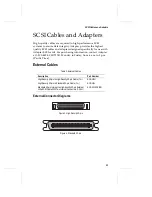
Page 29: ...tion contact Adaptec at 1 800 442 SCSI 7274 Monday to Friday from 6 a m to 5 p m Pacific Time External Cables External Connector Diagrams Table 3 External Cables Description Part Number High Density 5...

Page 30: ...3 position 2 peripherals adapter card standard 50 pin Internal Ultra SCSI 1 m ACK INT3 PNP 5 position 4 peripherals adapter card standard 50 pin Internal Ultra SCSI 1 5 m ACK INT5 PNP 3 position 2 pe...

Page 31: ...nectors on the SCSI Card 2930U2 Ultra2 Peripheral Terminator High density 68 pin Internal Ultra2 SCSI Cable SCSI Card 2930U2 Figure 8 Connecting Ultra2 Internal Peripherals Ultra2 Peripheral Terminato...

Page 32: ...tra2 Internal and Fast Ultra Narrow External Peripherals Ultra2 Peripheral Terminator High density 68 pin Internal Ultra2 SCSI Cable SCSI Card 2930U2 Fast Ultra Narrow Peripheral Terminated 50 pin Ext...

Page 33: ...MBytes sec 1 1 Mixing Fast Ultra peripherals with Ultra2 peripherals on the same segment causes the entire SCSI bus to default to Ultra SCSI speeds and cable requirements 15 3 m 9 8 ft Fast SCSI 10 MB...

Page 34: ......

Page 35: ...on in the U S and other countries used under license All other trademarks are owned by their respective owners Changes The material in this document is for information only and is subject to change wi...

Page 36: ...f and on the user is encouraged to try to correct the interference by one or more of the following measures Reorient or relocate the receiving antenna Increase the separation between equipment and rec...

Page 37: ...at any time by destroying the Software including the related documentation together with all copies or modifications in any form Adaptec will have the right to terminate your license immediately if yo...

Page 38: ...stand it and that by opening the package you agree to be bound by its terms and conditions You further agree that it is the complete and exclusive statement of the agreement between Adaptec and you wh...

Page 39: ...ec at 691 South Milpitas Boulevard Milpitas CA 95035 800 959 7274 THIS LIMITED WARRANTY DOES NOT EXTEND TO ANY PRODUCT WHICH HAS BEEN DAMAGED AS A RESULT OF ACCIDENT MISUSE ABUSE OR AS A RESULT OF UNA...

Page 40: ......

Page 41: ......

Page 42: ......

Reviews: