4-8
AEC-4412B/7412B User’s Guide
AEC-4412B/7412B User’s Guide
Stock Number: 511640-00 Rev B
Page: 4-8
Print Spec Number: 497358-00
Current Date: 3/19/98
ECN Date: 3/20/98
■
Caching
■
Control mode
These pages are mainly for informational purposes. None of the
fields in these pages are changeable except for write cache enable
and read cache disable in the caching page. Refer to the SCSI-2 spec-
ification for the format of these mode pages. The rigid disk geome-
try and format device pages are supported to provide certain host
operating systems information they need to do high-level formats.
The information within them is calculated by the AEC-4412B/7412B
based on the current array configuration.
In the caching page the write cache enable (WCE) and read cache
disable (RCD) bits apply only to the LUN the mode select command
was issued to. For example, write back and read cache may be con-
trolled on a per LUN basis.
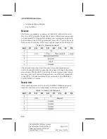
Read 6 and Read 10
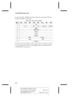
The AEC-4412B/7412B will support 6 and 10 byte read CDBs. Table
4-6 describes the Read 6 command, Table 4-7 describes the Read 10
command.
In the six byte Read CDB, a transfer length of zero indicates 256 log-
ical blocks are transferred.
Table 4-6. Read 6 Command
Byte#
Bit7
Bit6
Bit5
Bit4
Bit3
Bit2
Bit1
Bit0
0
08h
1
LUN
(MSB)
2
Logical Block Address
3
(LSB)
4
Transfer Length
5
Reserved


