background image

ADASH Ltd. 


Adash 3600-MPX


ADASH Ltd., Czech Republic, tel.: +420 596 232 670, fax: +420 596 232 671, email: info@adash.cz 

For next technical and contact information visit www.adash.net,  www.adash.cz 

3

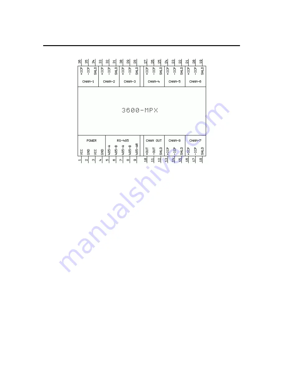
Terminal Board of the Adash 3600-MPX Module 


Fig. Terminal board of the Adash 3600-MPX module 


The display of the terminal board corresponds to the front view of the module. 
 

Description of Module Terminal Connectors 


POWER


supply voltage (terminal connectors with the same marking are interconnected inside): 

VCC 


+5 V / max. 200 mA, 

GND  

V. 


RS-485


communication connection for the Adash 3600 system (terminal connectors with the 
same marking are interconnected inside): 

485-A   

signal A of RS-485, 

485-B   

signal B of RS-485, 

485-AR  

termination resistance 120R, for the termination of the interface to connect to terminal 
connector 485-B. 


CHAN OUT


output of the multiplexed signal: 

+ OUT   

positive pole of the signal (without direct-current separation), 

 - OUT   

negative pole of the signal, 

SHLD  

cable 

shield. 


CHAN-1 .. CHAN-8


inputs of signals from sensors 1 to 8: 

+ ICP   

positive pole of ICP supply and the signal, 

 - ICP   

negative pole of the supply and the signal, 

SHLD   

sensor cable shield. 


Summary of Contents for 3600-MPX

Page 1: ...N unit just now Three operating modes ALL cyclic display data of all set channels USER display data of the selected channel MAX display data of the channel with the highest vibrations User configuration of measuring channels via the Adash 3600 Setup program User definition up to four different measurements for each channel via the Adash 3600 Setup program Capability to connect up to 8 these module...

Page 2: ...ntents Terminal Board of the Adash 3600 MPX Module 3 Description of Module Terminal Connectors 3 Description of Adash 3600 MPX 4 Description of Module Control 4 Extending the Set with the Adash 3600 MPX Module 6 The Set with a Number of Adash 3600 MPX Modules 7 Recommended Procedure of Module Connection 8 Technical Specification of Adash 3600 MPX 12 Dimensioned Sketch of Adash 3600 MPX 12 ...

Page 3: ...e interconnected inside VCC 5 V max 200 mA GND 0 V RS 485 communication connection for the Adash 3600 system terminal connectors with the same marking are interconnected inside 485 A signal A of RS 485 485 B signal B of RS 485 485 AR termination resistance 120R for the termination of the interface to connect to terminal connector 485 B CHAN OUT output of the multiplexed signal OUT positive pole of...

Page 4: ...X module and measured value display at the Adash 3600 MAIN module The selected mode is indicated by a green indicator located under the Mode button Selected mode Manner of display ALL it displays cyclically the state of all the measured channels MAX it displays the state of the channel with the highest vibrations in compliance with ISO USER it displays continuously the state of the selected channe...

Page 5: ... then the measured values at the selected channel remain displayed continuously Immediately after pushing the Channel button the decimal point switches on the indicator of the selected channel number and it remains on until the Adash 3600 MAIN module updates the measured values on its displays As soon the valid values measured at the selected channel are displayed on the displays the decimal point...

Page 6: ...or next technical and contact information visit www adash net www adash cz 6 Extending the Set with the Adash 3600 MPX Module The connection of the Adash 3600 MPX module to the Adash 3600 set is done according to the following schematic Fig Schematic of connection of the 3600 MPX module to the Adash 3600 system ...

Page 7: ...lic tel 420 596 232 670 fax 420 596 232 671 email info adash cz For next technical and contact information visit www adash net www adash cz 7 The Set with a Number of Adash 3600 MPX Modules Fig Interconnection of MPX output OUT terminal connectors ...

Page 8: ...0 COM Fig Interconnection at the end module 3600 COM At the end module of the set in this case 3600 COM there is a resistance termination of RS 485 via an interconnection of terminal connectors 485 B and 485 AR This interconnection must be removed and installed at the end module of the extended set in this case 3600 MPX 3 Interconnection of supply terminal connectors VCC and GND The supply conduct...

Page 9: ...tified by the following colours in the supplied set white conductor signal A of RS 485 black conductor signal B of RS 485 5 Connection of terminal connectors of the output signal from the Adash 3600 MPX module OUT OUT to the input terminal connectors of the Adash 3600 MAIN module ICP ICP via a shielded conductor The shield is connected to the SHLD terminal connectors of both the modules The interc...

Page 10: ...ors of the 3600 MAIN and 3600 MPX modules 6 Connection of vibration sensors To connect vibration sensors with ICP supply to the Adash 3600 set a special shielded twisted cable is supplied which is marked and connected as follows Conductor Sensor Module colour terminal connector terminal connector Shielding braiding SHLD White A ICP White blue black B ICP Fig Connection of channel 1 Fig Connection ...

Page 11: ... ICP ICP SHLD Fig Connection of channels 7 and 8 7 Replace the terminal connector covers The extension of the Adash 3600 set with the 3600 MPX module is completed and the system is ready for measurement Channel 7 NOTICE Each module of Adash 3600 system has individual unique internal address on RS 485 see User s guide Vibration Monitoring System Adash 3600 3600main com pwr_man_en pdf List of Module...

Page 12: ...lected vibration sensor Interface RS 485 for the communication between the Adash 3600 set modules Control by the main unit of Adash 3600 MAIN selection of the mode and channel by means of the buttons on the front module panel Unit setting using the 3600 Setup program via communication unit Adash 3600 COM or Adash 3600 NET Protection IP20 Temperature range 10 C to 50 C Supply 5 V 200 mA Dimensions ...

Reviews: