USER’S MANUAL
V-line 899x.xxx/LPG HYBRID
29
4.7.
SOPA design
On Client’s special request the dispenser in service mode can be equipped with magnetic release switch
(SOPA design). The operator of the filling station can release the dispenser for single filling operation in
this mode. After nozzle lifting the displays are reset and fuel filling is started. After hanging up the
nozzle, the dispensed volume and quantity values are permanently displayed until the dispenser is
magnetic released and the dispensing nozzle is lifted off subsequently. The red signal light informs both
the operator and the customer about the condition of the dispenser.
4.8.
Design with heating of the electronic case
On the special customer´s requirement the fuel dispenser can be delivered with heating of electronic case
by heater 250 VA. For feeding of the heating is used an individual cable - see the enclosure no. 16.
5.
TECHNICAL DATA
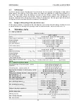
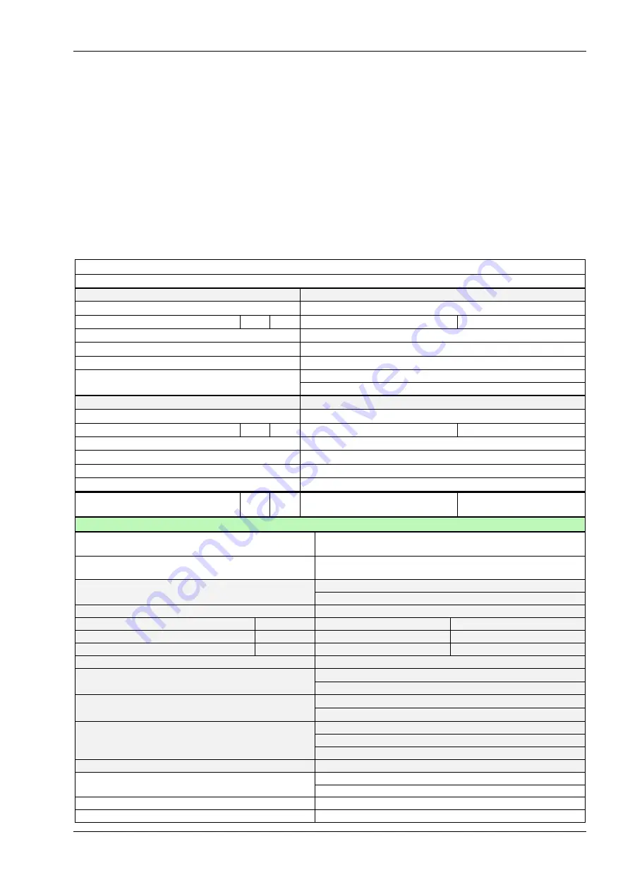
5.1. Basic parameters
Electronic counter
ADP1/T, ADP2/T
Display
Iluminated LCD - BACK LIGHT DISPLAY (BLD)
Power supply of electronics
U
nap
P
nap
1/N/PE AC 230 V ±15 %, 50 Hz
input 85 VA
Volume displayed
6 digits with the setting of digit position
Price displayed
6 digits with the setting of digit position
Unit price displayed
4 digits with the setting of digit position
Total volume counter
electromechanical - 7 digits
electronically - 11 digits
CDC
Display
Iluminated LCD - BACK LIGHT DISPLAY (BLD)
Napájení elektroniky
U
nap
P
nap
1/N/PE AC 230 V ±15 %, 50 Hz
Příkon 120 VA
Volume displayed
6 digits with the setting of digit position
Price displayed
6 digits with the setting of digit position
Unit price displayed
4 digits with the setting of digit position
Total volume counter
electromechanical - 7 digits
Power supply of electronic case
heating
U
nap
P
nap
1/N/PE AC 230 V ±15 %, 50 Hz
input 250 VA
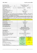
5.1.1. Modul for petrol or diesel
Connecting flange of the suction piece – suction
system (S)
DN 40 with inner thread G 1 1/2―
pro Q = 40, 60, 70, 80 dm
3
.min
-1
Connecting piece – pressure system (P)
DN 40 with outer thread G 1 1/2―
pro Q = 40, 60, 70, 80 dm
3
.min
-1
Required inner diameter of suction piping – suction
system (S
)
DN 40 for flowrate Q = 40, 60 dm
3
.min
-1
DN 50 for flowrate Q = 70, 80 dm
3
.min
-1
Piping innner diameter required – pressure syst. (P)
DN 40 for flowrate Q = 40, 60, 70, 80 dm
3
.min
-1
Max. flowrate Q
max
1)
dm
3
.min
-1
40, 60
70, 80
Min. flowrate Q
min
1)
dm
3
.min
-1
4
5
Min. measured quantity (MMQ)
dm
3
2
5
Accuracy of measurement
± 0,5 %
Max. operating pressure p
max
Pro Q
max
= 40 – 60 dm
3
.min
-1
– 0,25 MPa
Pro Q
max
= 70 – 80 dm
3
.min
-1
– 0,32 MPa
Min. operating pressure p
min
Pro Q
max
= 40 – 60 dm
3
.min
-1
– 0,12 MPa
Pro Q
max
= 70 – 80 dm
3
.min
-1
– 0,19 MPa
Ambient operating temperature
Basic -20°C to +40°C
Standard -20°C to +50°C
Special -30°C to +60°C / -40°C to +60°C
Medium temperature
-20°C to +50°C
Filtering property
30 µm for petrol
30 µm for diesel (60 µm -
for extreme minus temperatures
)
Reach of dispensing hose
4 to 6 m
Max. level of noise
<70 dB


