USER’S MANUAL
V-line 899x.xxx/LPG HYBRID
52
17.2.
Hydraulic parts for dispensing LPG
The dispenser can be joined only to process equipment (tanks, piping) of perfect tightness and cleanness.
The supplier of the process equipment is responsible for its tightness and cleanness.
The dispenser installation is carried out by the organisation authorised by the manufacturer.
Prior to
the installation the organisation shall perform the inspection of used power and communication cables.
When the dispenser is installed, they shall check the tightness, function of hydraulic equipment of the
dispenser, supply piping and fittings. They also check power and communication cables including their
lines and fixing. At least 100 dm
3
of LPG has to be discharged from each dispensing nozzle with Q
max
.
Prior to official metrological testing the dispenser (every dispensing nozzle) has to operate for min. 5
minutes in max. flow rate.
ATTENTION!
The process and service equipment of filling stations can be operated only when they have been
built up according to the approved design and on the basis of positive result of licence regime.
17.3.
Hydraulic section
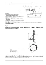
Seat and set in concrete the levelled steel base frame – delivered on special request by dispensers’
manufacturer – on the shaft with the supply pipeline and return piping from the storage tank.
In case the customer makes use of his own base frame, the frame must meet the requirements of the
sufficient rigidity, flatness and proper positions of fixing holes.
It is recommended to fasten the frame to a pedestal approximately 200 mm over the terrain for the
reason of easier assembly and handling or servicing purposes. The shaft, after having connected the piping
and the electric conductors to the dispenser, should be filled at least to the terrain level in order to
prevent the propane-butane gas from accumulating in the well and caverns for being heavier than air.
Attach the dispenser to the embedded frame.
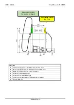
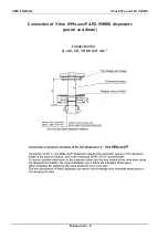
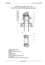
The dispenser requires the connection to the return DN 16 piping. The separator return piping involves a
metrological branch provided with a G ½ ‖ spherical cock designed to metrological verification of the
dispenser and the servicing purposes. The return piping of DN 16 connected to the storage tank is jointed
to the G 1/2" inner thread of the gaseous phase separator piping. The inlet piping of DN 19 at least from
the LPG pumping unit is connected to the G 3/4" inner thread of the spherical cock in the separator input.
The manufacturer recommends to seal the bolted joints with the white tape of PTFE – FLEXON material
0.1 mm thick.
IMPORTANT NOTICE!
ACCORDING TO THE SAFETY REASONS THE HYDRAULIC SYSTEM OF THE FUEL DISPENSER MUST BE
PERMANENTLY CONNECTED BY THE HELP OF RETURN PIPING OF GASEOUS PHASE IN THE INSIDE SPACE
OF LPG PRESSURE TANK.
IN CASE OF STOP-ELEMENT INSTALLATION (ELECTROMAGNETIC VALVE) INTO THE RETURN PIPING OF
GASEOUS PHASE BETWEEN THE FUEL DISPENSER AND TANK MUST BE THE RETURN PIPING BETWEEN
THE FUEL DISPENSER AND STOP-ELEMENT EQUIPPED WITH THE SAFETY VALVE WITH SETTING MAX.
OPENING PRESSURE 2,5 MPa.
IMPORTANT NOTICE!
In accordance with the article 4.4.1.2 EN 14678-1 the input piping of the liquid phase and return piping
of the gaseous phase should be connected to the connecting piping of the dispenser through a shear
valve - safety breakage coupling which prevents the substance leaking in case of dispenser failure. The
bending moment value for the breaking of the coupling should range within 300 to 600 Nm.
Breakage couplings of the liquid and gaseous phases should be anchored to the lower machinery in
the shaft under the dispenser.
Approved breakage coupling is delivered on special request of the Client.
17.4.
Wiring
Earthing conductor shall be connected to the shaft under every dispenser.

