USER’S MANUAL
V-line 899x.xxx/LPG HYBRID
56
21.
SPARE PARTS CATALOGUE
Spare parts catalogues of the dispenser are supplied to service organisations. The user can request the
spare part catalogues from the manufacturer.
22.
ACCESSORIES
Parts of the dispenser delivery:
Shipping pallet - dismounted at the dispenser shaft site.
Set for hydraulic system connection to V-line 899x.xxx/S dispensers (Enclosure No. 7):
- connecting pieces (suction corrugated pipe) are either screwed to the filter of the monoblock or
enclosed extra
- threaded flanges for the supply piping
- O-rings for connecting pieces
- cover of the inlet opening
Set for hydraulic system connection to V-line 899x.xxx/P dispensers (Enclosure No. 8):
- connecting piece
- packing
Set of parts for the connection of vapour recovery system (Enclosure No. 7)
Set for the dispenser connection to the base frame - special washers (Enclosure No. 7)
Set of el. parts (Enclosure No. 13 – 15)
- ATEX plug
Set of el. parts (Enclosure No. 13 – 15)
- ATEX bushing
The delivery of the dispenser is not:
—
KL-MANINF infrared manager keyboard
- for the selection of unit prices and display of
electronic totalizers
for dispensers not connected to the control system
of the filling
station (service operation of the filling station) -
can be ordered when ordering the
dispenser, or as a spare part under number 9046800802.
On the special order the basic frame
23.
DOCUMENTATION DELIVERED
User´s manual
EC Declaration of Conformity
Service manual
24.
ENCLOSURES
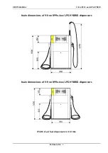
Enclosure No. 1
Main dimensions of dispensers V-line 899x.4xx/LPG HYBRID
,
V-line 899x.6xx/LPG HYBRID
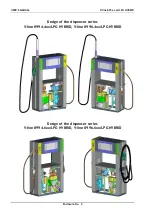
Enclosure No. 2
Design of the dispenser series V-line 8994.4xx/LPG HYBRID,
V-line 8996.4xx/LPG HYBRID, V-line 8994.6xx/LPG HYBRID,
V-line 8996.6xx/LPG HYBRID
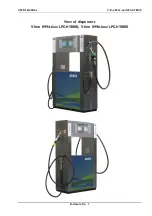
Enclosure No. 3
View of dispensers V-line 8994.6xx/LPG HYBRID, V-line 8996.6xx/LPG HYBRID
Enclosure No. 4
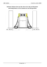
Min. distances of the dispenser from a steady obstacle located at the filling station
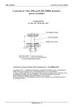
Enclosure No. 5 - 6 Installation dimensions of V-line 899x.xxx/LPG HYBRID dispensers
Enclosure No. 7
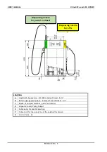
Installation dimensions of V-line 899x.xxx/S/LPG HYBRID – for petrol and diesel;
with vapour recovery
Enclosure No. 8
Installation dimensions of V-line 899x.xxx/P/LPG HYBRID – for petrol and diesel
Enclosure No. 9
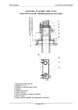
Connection of satellite outlet at the V-line 899x.xxx/LPG HYBRID (for diesel)
Enclosure No. 10
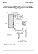
Areas with risk of gas pressure release or residual nitrogen at the separator used in
the hydraulic circuit of LPG module
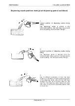
Enclosure No. 11
Dispensing nozzle positions during fuel dispensing (petrol and diesel)

