The Power Supply circuitry can be turned On and Off via the main power switch in the lower right corner of
.
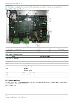
Figure 4: ACE2 Main Circuit Board
1. Ribbon connector to display board
3. SW1
5. SW7
7. Relay Fuses
2. Main PCB
4. SW2
6. RY7
Table 1: Main Board Description
Feature
Function Description
Ribbon connector to display
board
Main PCB
SW1
Reset switch - Press to reset the processor
SW2
Two-position DIP switch
•
Not used
•
Keep in On position
SW7
On/Off power switch to ACE2
RY7
RY7 general fault relay
Relay Fuse
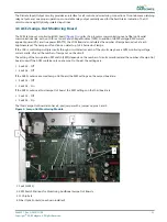
ACE2 Power Supply Circuit
The ACE2 Power Supply circuitry is integrated into the Main Circuit Board (shown in
). It provides the internal system
with a regulated and isolated power source.
ACE2 Input/Output
Advanced Control Equipment (ACE2)
Introduction
10
Copyright
©
ADB Safegate, All Rights Reserved
Summary of Contents for ACE2
Page 1: ...Advanced Control Equipment ACE2 User Manual 96A0357 Rev G 2019 11 08 ...
Page 2: ......
Page 18: ...Advanced Control Equipment ACE2 Introduction 12 Copyright ADB Safegate All Rights Reserved ...
Page 42: ...Advanced Control Equipment ACE2 Parts 36 Copyright ADB Safegate All Rights Reserved ...
Page 46: ......


