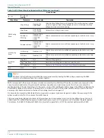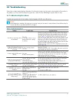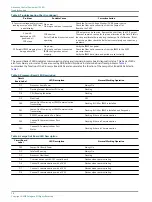
Table 4: Troubleshooting Chart (continued)
Problem
Possible Cause
Corrective Action
8. Incorrect voltageand/or current
reading occurs on the ACE2 front
panel display.
No power.
Fiber optic cable not connected.
Check the Current Voltage Monitor (CVM) power source.
Check the fiber optic connection from the Lamps-Out
Board to the CVM.
9. Low VA
displayed on LCD
panel and all
CCR steps.
CCR shorted
Part of field load is shorted or not
operating.
CCR output may be shorted. Remove the short from the CCR output.
The most common reason for this is an alteration of the field. If this is
the case recalibrate the load using the Lamps-Out Calibration. If that
is not the problem check the field circuit completely and correct any
problems.
10. Periodic IRMS megging is not
being performed
No power.
Fiber optic cable not connected.
IRMS configuration not set
properly.
Verify the IRMS has power.
Check the fiber optic connection from the IRMS to the ACE2
processor board.
Verify the IRMS date, time, and period are set correctly.
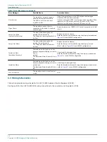
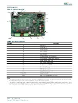
The second bank of LEDs indicates communication status and internal processor board diagnostic status. This bank of LEDs
also form binary error codes. These are used by ADB Airfield Solutions to determine board level problems.
summarizes the function of the Processor Board LEDs and enumerates the function of the Lamps-Out Board LEDs listed in
.
Table 5: Processor Board LED Description
Circuit
Board Label
LED Description
Normal Working Operation
D1
Processor board Power
Always On
D7
Flashing Interval Indicates CPU Load
Flashing
D8
CPU Running Indication
Flashing
D9
Not Used
Off
D10
Lamps-Out Monitoring or IRMS Communication
Transmitting
Flashing if LOM or IRMS is Installed
D11
Lamps-Out Monitoring or IRMS Communication
Transmitting
Flashing if LOM or IRMS is Installed and Responds
D12
RS232 Communication Port Status
Flashing if there is Communication
D13
Channel B Communications Port
Status
Flashing if there is Communication
D15
Channel A Communications Port
Status
Flashing if there is Communication
Table 6: Lamps-Out Board LED Description
Circuit Board
Label
LED Description
Normal Working Operation
D10
Lamps-Out Board Power
Always On
D2
Idle Task Running
Always On
D3
Processor Heartbeat
Flashing
D4
Communications with ACE2 control board
Flashes when communicating
D6
Channel 0 communications with a CVM
Flashes when communicating
D7
Channel 1 communications with a CVM
Flashes when communicating
D8
Channel 2 communications with a CVM
Flashes when communicating
Advanced Control Equipment (ACE2)
Troubleshooting
28
Copyright
©
ADB Safegate, All Rights Reserved
Summary of Contents for ACE2
Page 1: ...Advanced Control Equipment ACE2 User Manual 96A0357 Rev G 2019 11 08 ...
Page 2: ......
Page 18: ...Advanced Control Equipment ACE2 Introduction 12 Copyright ADB Safegate All Rights Reserved ...
Page 42: ...Advanced Control Equipment ACE2 Parts 36 Copyright ADB Safegate All Rights Reserved ...
Page 46: ......

