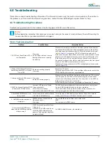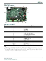
6.2 Error Messages
Table 7: Error Messages
Error Message
Possible Cause
Corrective Action
Lcl
(Local Control)
This message is located on the
bottom of the LCD screen in smaller
lettering
The regulator has been turned into
Local
Control mode.
N/A
Rmt
(Remote Control)
This message is located on the
bottom of the LCD screen in smaller
lettering
The regulator has been turned into
Remote
Control mode.
N/A
LoP
(Loss of Power)
This message is located on the
bottom of the LCD screen in smaller
lettering
There is a loss of main power in the
regulator.
The Input wiring may be damaged
Restore power to the Regulator.
Locate the input that monitors the Primary Power at J4 Pin 9
) see specific wire diagram for the situation, and
make sure connection is being made.
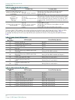
COM A Failure
The ACE2 is configured for ACLS
mode, but is meant to be a Stand-
Alone system.
The ACE, ACE2 or Vault that is
connected though COM A is not
powered up.
The COM A cable is unplugged or
loose.
Call ADB Airfield Solutions for assistance if this is the situation
Power up the other unit.
Check to ensure the cable is securely attached to the ACE2, as
well as the other unit to communicate with.
COM B Failure
The ACE2 is configured for ACLS
mode, but is meant to be a Stand
Alone system.
The ACE, ACE2, or Vault that is
connected though COM B is not
powered up.
The COM B cable is unplugged or
loose.
Call ADB Airfield Solutions for assistance if this is the situation.
Power up the other unit.
Check to ensure the cable is securely attached to the ACE2,
and to the other unit.
Pr Power Failure
(Primary Power Failure)
There is a loss of main power in the
regulator.
The Input wiring may be damaged
Restore power to the Regulator.
Locate the input that monitors the Primary Power at J4 Pin 9
) see specific wire diagram for the situation, and
make sure connection is being made.
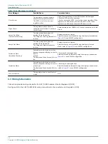
Low VA
The ACE2 is not correctly calibrated.
The regulator has a bad field circuit
or has become shorted.
Run though the Lamps-Out Calibration; during that process
the ACE2 calibrates the system.
Recalculated the present load, and adjust accordingly.
Incorrect Current
(Incorrect Current)
ACE2 configuration does not match
regulator.
The ACE2 is not properly reading the
steps of the regulator. (In Stand-
Alone Only)
The regulator is not outputting the
correct current levels.
Make sure that the ACE2 is configured for 3
Step or 5 Step depending on the regulator. Ensure the
regulator is set to 6.6A or 20A depending on the regulator
type.
In the lower left corner of the LCD screen, the step of the
regulator is displayed, if this does not match the actual step,
there is a problem with the internal wiring. See wiring
diagrams.
There is an internal problem in the regulator; call ADB Airfield
Solutions for further assistance. Return CCR to RMT control.
Protective Shutdown CHECK THE
CALLOUT (Protective Shutdown)
The regulator had an error such as
Open Circuit or Low VA and was shut
down. The regulator was
commanded On but has no output
current.
Check the Regulator for open connections and visible damage.
Restart the system.
96A0357, Rev. G, 2019/11/08
29
Copyright
©
ADB Safegate, All Rights Reserved
Summary of Contents for ACE2
Page 1: ...Advanced Control Equipment ACE2 User Manual 96A0357 Rev G 2019 11 08 ...
Page 2: ......
Page 18: ...Advanced Control Equipment ACE2 Introduction 12 Copyright ADB Safegate All Rights Reserved ...
Page 42: ...Advanced Control Equipment ACE2 Parts 36 Copyright ADB Safegate All Rights Reserved ...
Page 46: ......

