background image

A second CVM is connected to the input of the CCR to measure these parameters. If these functions are enabled, the display

shows the following hour-meter parameters:

Total time the CCR has been ON xHT.

Time the CCR has been on Step B1 xH1.

Time the CCR has been on Step B2 xH2.

Time the CCR has been on Step 3 xH3.

Time the CCR has been on Step 4 xH4.

Time the CCR has been on Step 5 xH5.

Total number of the CCR OFF-ON switching cycles xC.

Note

Small x = time in hours.

Push-button 3, Select/Config, becomes active and is used only in a stand-alone L-827 or L-829 mode of operation, described

above in Push-button 2.
Push-button 4, Software Version, initiates the automatic sequence displaying the following system parameters:

Main Control Board Firmware Version.

Lamps-Out Monitor Firmware Version.

IRMS Firmware Version.

RS422 channel A network address.

RS422 channel A baud rate.

RS422 channel B network address

RS422 channel B baud rate.

Appearance of question marks instead of the firmware version number means the firmware is not loaded for that function.

4.3 I/O Status display

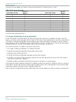
Pressing and holding push-button 4 during the Software Version sequence displays the status of the Input/Output Interface.

In this mode, read all the input and output lines. The format appears like this:

Out 87654321

or

Out

_ _ _ _ _ _ _ _

Inp 87654321

Inp

_ _ _ _ _ _ _ _

Or a combination of the two.
Each number is linked to a different pair of pins on the input or on the output connector. If the number is displayed, the

corresponding pair of input pins has voltage on them and the corresponding relay is closed.

Note

Out ?????? means there is nothing written to the outputs since power-up and the latching relay status is unknown.

96A0357, Rev. G, 2019/11/08

17

Copyright 

©

 ADB Safegate, All Rights Reserved

Summary of Contents for ACE2

Page 1: ...Advanced Control Equipment ACE2 User Manual 96A0357 Rev G 2019 11 08 ...

Page 2: ......

Page 3: ...d are guaranteed to be merchantable and fit for the ordinary purposes for which such products are made ADB SAFEGATE L858 Airfield Guidance Signs are warranted against mechanical and physical defects in design or manufacture for a period of 2 years from date of installation per FAA AC 150 5345 44 applicable edition Note See your sales order contract for a complete warranty description All Products ...

Page 4: ...SAFEGATE replacement parts or accessories Failing to make sure that auxiliary equipment complies with approval agency requirements local codes and all applicable safety standards if not in contradiction with the general rules Using materials or auxiliary equipment that are inappropriate or incompatible with your ADB SAFEGATE equipment Allowing unskilled personnel to perform any task on or with the...

Page 5: ...sh button Description 16 4 3 I O Status display 17 4 3 1 Lamps Out Calibration for Stand Alone Mode 18 5 0 Installation 19 5 1 Introduction 19 5 2 Wall Mount Installation 19 5 2 1 ACE2 Cabling Entry 20 5 3 Internal Mount Installation 23 5 4 Combo Box Mount Installation 23 5 4 1 ACE2 Cable Entry 25 6 0 Troubleshooting 27 6 1 Troubleshooting Procedures 27 6 2 Error Messages 29 6 3 Wiring Schematics ...

Page 6: ...Advanced Control Equipment ACE2 TABLE OF CONTENTS vi Copyright ADB Safegate All Rights Reserved ...

Page 7: ...o observe this warning may result in personal injury death or equipment damage ARC Flash may cause blindness severe burns or death WARNING Wear personal protective equipment Failure to observe may result in serious injury WARNING Do not touch Failure to observe this warning may result in personal injury death or equipment damage CAUTION Failure to observe a caution may result in equipment damage Q...

Page 8: ...safety devices as specified by applicable safety regulations If safety devices must be removed for installation install them immediately after the work is completed and check them for proper functioning prior to returning power to the circuit Failure to follow this instruction can result in serious injury or equipment damage Additional Reference Materials Important Information IEC International St...

Page 9: ...cessary to Install Carry out maintenance Carry out troubleshooting on the Advanced Control Equipment 2 2 How to work with the manual 1 Become familiar with the structure and content 2 Carry out the actions completely and in the given sequence 96A0357 Rev G 2019 11 08 3 Copyright ADB Safegate All Rights Reserved ...

Page 10: ...Advanced Control Equipment ACE2 Advanced Control Equipment 4 Copyright ADB Safegate All Rights Reserved ...

Page 11: ...The ACE2 can operate either as the remote interface between the L 890 ALCMS and any controlled element in the airfield lighting vault or as the stand alone constant current regulator CCR monitor performing all L 827 L 829 functions in accordance with FAA AC 150 5345 10 The ACE2 is a universal device that can be used to control any type of CCR and or controlled element regardless of the manufacture...

Page 12: ...erver stays in constant communication with all the ACE2 and ACE units in both of the networks while at the same time staying in constant contact with the main ALCMS network This communications protocol dictates that the local ACE2 store all data and parameters specific to the controlled element This characteristic frees up the ALCMS computers from having to store the parameters for each of the con...

Page 13: ...alf is reserved for warning and alarm messages in reverse color Reverse color means that the background is white and the text is blue The second string is split to indicate several fields and displays Brightness step Reverse color means protective shutdown blank OFF Remote Rmt Local Lcl reverse color Primary power present PP loss of power LoP reverse color RS422 channel A message received A RS422 ...

Page 14: ...s of CCRs and or controlled elements regardless of the manufacturer The ACE2 printed circuit boards are mounted inside a small and rugged environmental enclosure that can be wall mounted placed on a CCR or enclosed in the CCR itself The ACE2 consists of microprocessor based module s that process communication control commands input output interface and failsafe functionality for controlled element...

Page 15: ... Off Connecting pins 1 and 2 enables the watchdog timer Connecting pins 2 and 3 disables watchdog timer and removing the jumper also disables watchdog timer The normal setting for the watchdog timer is On The watchdog timer should only be set by qualified ADB Airfield Solutions personnel The reset switch SW1 is used during the design and test phase and has no application for the user The keypad sw...

Page 16: ...ector to display board Main PCB SW1 Reset switch Press to reset the processor SW2 Two position DIP switch Not used Keep in On position SW7 On Off power switch to ACE2 RY7 RY7 general fault relay Relay Fuse ACE2 Power Supply Circuit The ACE2 Power Supply circuitry is integrated into the Main Circuit Board shown in Figure 5 It provides the internal system with a regulated and isolated power source A...

Page 17: ...he CCR is controlling multiple circuits through circuit selectors each of the circuits may have a CVM monitoring voltage current watts VA and the number of lamps out on the circuit The setting of the two position DIP switch SW1 depends on the number of circuits monitored and the number of Lamps Out boards used If the ACE2 contains only one Lamps Out board the settings are Switch 1 Off Switch 2 Off...

Page 18: ...Advanced Control Equipment ACE2 Introduction 12 Copyright ADB Safegate All Rights Reserved ...

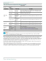
Page 19: ...ion 2 3 2 3 1 modify Menu Item Parameter Possible value Description CCR Config Menu CCR Type Generic Heavy Duty Heavy Duty is an older brand name which requires an additional output line B1 B10 to turn on and off the regulator If this regulator is not in use adjust setting to Generic CCR Class 6 6A 20A ADB Safegate sells two regulator output types 6 6A and 20A output Based on the regulator choose ...

Page 20: ...ns Exit N A N A Note VA refers to the Volt Amps in an airfield load and is measured by reading the RMS voltage measuring the RMS current and multiplying these two numbers together Watts corresponds to the amount of power actually consumed by an airfield load These two numbers are only equal in the case of a purely resistive load In systems with reactance capacitance or inductance power from the so...

Page 21: ... Now command initiates an immediate insulation resistance measurement regardless of the schedule The Meg Timer Reset restarts the megging schedule The next megging shall occur at the end of the Meg Period and periodically after that 96A0357 Rev G 2019 11 08 15 Copyright ADB Safegate All Rights Reserved ...

Page 22: ... list of the monitored parameters Amps Output CCR current A Volts Output CCR voltage V VA Output CCR VA VA Watts Output CCR watts W LO Number of lamps out on the lamp circuit optional Ohms The last insulation resistance reading for the lamp circuit Ω optional Cycle Above list cycled Pushbutton 2 Auxiliary Monitor optional if the function is enabled provides access to the CCR input power parameters...

Page 23: ...sion IRMS Firmware Version RS422 channel A network address RS422 channel A baud rate RS422 channel B network address RS422 channel B baud rate Appearance of question marks instead of the firmware version number means the firmware is not loaded for that function 4 3 I O Status display Pressing and holding push button 4 during the Software Version sequence displays the status of the Input Output Int...

Page 24: ...te lamp out detection In all modes of operation the calibration is performed in this order 1 The number of initially present lamps out is entered in the ACE2 2 The ACE2 steps through all brightness steps and takes measurements 3 One Lamp is removed from the circuit 4 The ACE2 steps through all brightness steps again and takes measurements 5 At this time it records the Current and Voltage values fo...

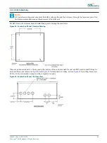
Page 25: ...specifications for specific installation instructions The installation conforms to the applicable sections of the National Electric Code and local codes The ACE2 is mounted either as a Remote mount a Wall mount a Combo Box mount or an Internal mount The following subsections describe each of these mounting options 5 2 Wall Mount Installation Figure 9 shows the exterior of the ACE2 wall mount Figur...

Page 26: ...nclosure shown in Figure 14 2 Remove the ACE2 unit and drill the marked holes Insert anchor hardware as required DO NOT DRILL THOUGH THE BOX Drilling chips and debris can not fall into the enclosure 3 Carefully open the lid of the enclosure Use 20 x 1 0 inch long screws flat washers and lock washers to fasten the enclosure to the wall or to rails 4 Mount the enclosure using the top two holes then ...

Page 27: ...ns and the Conduit Drawing Figure 14 for routing Power and ACE to ACE communication wiring must be in separate conduits Attach all conduits as required to the bottom or to the top access plate ONLY as seen in Figure 14 Protect ALL electronic equipment in the ACE2 enclosure while installing conduit Figure 11 Wall Mount Bottom View Figure 12 Wall Mount Top View 96A0357 Rev G 2019 11 08 21 Copyright ...

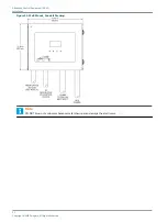
Page 28: ...re 13 Wall Mount Conduit Drawing Note DO NOT blow out enclosures because metal shavings can damage the electronics Advanced Control Equipment ACE2 Installation 22 Copyright ADB Safegate All Rights Reserved ...

Page 29: ...er is required The ACE2 is located on the interior attached to the hinged door To gain access to the ACE2 open the CCR door unlatch and open the ACE2 enclosure door See Figure 14 Figure 14 Internal Mount External View Figure 15 Internal Mount Interior View 5 4 Combo Box Mount Installation Locate each ACE2 Combo Box unit as close as possible to each of the controllable elements like the Regulator t...

Page 30: ...he enclosure Refer to Figure 18 2 Remove the ACE2 unit drill out the marked holes and insert anchor hardware as required DO NOT DRILL THOUGH THE BOX to keep drilling chips and debris from falling into the enclosure 3 Carefully open the lid of the enclosure Use 20 x 1 0 inch long screws flat washers and lock washers to fasten the enclosure to the wall or to rails 4 Mount the enclosure using the top...

Page 31: ...electronics Figure 18 Combo Box Mount Interior Drawing There are six knockouts each in the top and in the bottom of the enclosure walls for one inch EMT metal conduit fittings for wires and fiber optic cables See Figure 18 and Figure 19 for dimensions in inches and see Figure 21 for routing Power and ACE to ACE communication wiring must be in separate conduits Figure 19 Combo Box Mount Bottom View...

Page 32: ...Figure 20 Combo Box Mount Top Detail Figure 21 Combo Box Mount Conduit Drawing Advanced Control Equipment ACE2 Installation 26 Copyright ADB Safegate All Rights Reserved ...

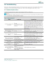
Page 33: ...n or Off Board not seating properly No power Reseat the PC board Cycle the power to the ACE2 If the problem still persists contact the ADB Airfield Solutions service representative 3 Lamps out board LEDs are not flashing No power Board not seated properly Make sure the power LED on the lamps out board is on If it is not on turn the power to the ACE2 off Check the integrity of the header connection...

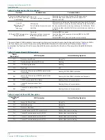
Page 34: ... determine board level problems Table 4 summarizes the function of the Processor Board LEDs and enumerates the function of the Lamps Out Board LEDs listed in Table 5 Table 5 Processor Board LED Description Circuit Board Label LED Description Normal Working Operation D1 Processor board Power Always On D7 Flashing Interval Indicates CPU Load Flashing D8 CPU Running Indication Flashing D9 Not Used Of...

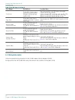
Page 35: ... to ensure the cable is securely attached to the ACE2 and to the other unit Pr Power Failure Primary Power Failure There is a loss of main power in the regulator The Input wiring may be damaged Restore power to the Regulator Locate the input that monitors the Primary Power at J4 Pin 9 Figure 22 see specific wire diagram for the situation and make sure connection is being made Low VA The ACE2 is no...

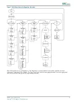
Page 36: ...ut passing the set threshold The Lamps out Alarm threshold is too low Replace burned out lamps Reset the Lamps out threshold using the display in stand alone refer to Figure 7 Or use ACLMS configuration Insulation Warn Insulation Warning Somewhere on the load a wire has become exposed allowing current to flow to ground The Insulation Alarm threshold is too low Check load for damaged lines Reset th...

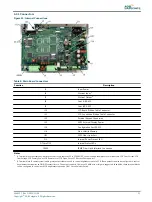
Page 37: ... 1 A Terminal block J4 accepts any discrete contact closure that uses 24 to 250V AC DC control voltage Examples of useful inputs are CCR Over Current CCR Over Voltage CCR Primary Power CCR Remote Local CCR Open Circuit CCR Access Door open etc 2 B Terminal block J5 carries system latching relay outputs that are used to control brightness steps of a CCR These outputs can also be configured to contr...

Page 38: ...igure 23 ACE2 PCB to URCII I PCB for CCF 3 and 5 Step CCR Figure 24 ACE2 PCB to CCT 3 and 5 Step Control PCB Advanced Control Equipment ACE2 Troubleshooting 32 Copyright ADB Safegate All Rights Reserved ...

Page 39: ...Figure 25 ACE2 Internal and Combo Box Wiring 96A0357 Rev G 2019 11 08 33 Copyright ADB Safegate All Rights Reserved ...

Page 40: ...Figure 26 ACE Combo Wall Mount Internal Advanced Control Equipment ACE2 Troubleshooting 34 Copyright ADB Safegate All Rights Reserved ...

Page 41: ...tity column contains the quantity required per unit assembly or subassembly The code AR As Required is used if the part number is a bulk item ordered in quantities or if the quantity per assembly depends on the product version or model The Note column contains letters that refer to notes at the end of each parts list Notes contain special ordering or product part version information 7 1 Parts List...

Page 42: ...Advanced Control Equipment ACE2 Parts 36 Copyright ADB Safegate All Rights Reserved ...

Page 43: ...all When you have an airfield lighting or system control system problem it is our goal to support airfield maintenance staff as quickly as possible To support this effort we ask that you have the following information ready before calling The airport code If not with an airport then company name prefer customer id number Contact phone number and email address Product with part number preferable or...

Page 44: ... as supplier components and sub contractor operations ADB SAFEGATE offers a recycling program for our products to all customers worldwide whether or not the products were sold within the EU ADB SAFEGATE products and or specific electrical and electronic component parts which are fully removed separated from any customer equipment and returned will be accepted for our recycling program All items re...

Page 45: ...act Tel 46 0 40 699 17 00 Fax 46 0 40 699 17 30 Email marketing adbsafegate com Internet www adbsafegate com ADB SAFEGATE Airfield Technologies Ltd China ADB SAFEGATE China Unit 603 D Block CAMIC International Convention Center No 3 Hua Jia Di East road ChaoYang district Beijing 100102 P R China Contact Tel 86 10 8476 0106 Fax 86 10 8476 0090 Email china safegate com Internet www adbsafegate com A...

Page 46: ......
Reviews: