6.0 Troubleshooting
This section contains troubleshooting information. The information covers only the most common problems. If a solution to
the problem is not found with the information given here, contact the local ADB Safegate representative for help.
6.1 Troubleshooting Procedures
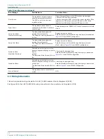
Troubleshooting procedures for the Advanced Control Equipment (ACE2) are in this section.
Note
Before beginning, remember that improper or incorrect wiring is the cause of most problems. Check all the wiring for
loose connections or possible electrical shorts/opens.
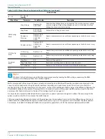
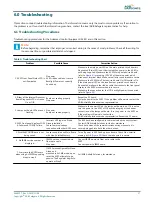
Table 4: Troubleshooting Chart
Problem
Possible Cause
Corrective Action
1. ACE2 Front Panel Status LCD is
not illuminated.
No power
ACE2 ribbon cable not secure
Backlight Power not correctly
hooked up.
Make sure the main power LED on the main printed circuit board is
illuminated. If this LED is not illuminated then power to the ACE2 is
not being supplied. Make sure the ACE2 Main printed circuit board
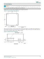
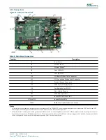
(refer to
) is receiving 120 VAC at the main power, quick
disconnect, terminal block. Make sure all wire connections are secure.
Make sure the ACE2 Main Printed circuit board On/Off switch is On.
If the main power LED on the input/output printed circuit board is
illuminated, make sure the ribbon cable that connects the front panel
display to the ACE2 processor board is secure.
Make sure the connection for the LCD backlight power is connected.
(refer to
)
2. Either of the Internal Processor
Board Diagnostic LEDs is frozen
On or Off.
Board not seating properly
No power
Reseat the PC board.
Cycle the power to the ACE2. If the problem still persists, contact the
ADB Airfield Solutions service representative.
3. Lamps out board LEDs are not
flashing.
No power
Board not seated properly
Make sure the power LED on the lamps out board is on. If it is not on,
turn the power to the ACE2 off. Check the integrity of the header
connection on the lamps out board. Turn the power to the ACE2 on.
If the problem still persists, contact the
ADB Airfield Solutions service representative. Reseat the PC board.
4. ACE2 front panel displays COM
A Failure and COM B Failure.
Incorrect ACE type in a Stand
Alone installation
Loose Communications
connection with other ACE2 units.
The ACE has been configured to communicate with a host system.
Contact ADB Airfield Solutions for further assistance.
Check both sides of the communications wiring make sure it is
securely plugged into both the other devices.
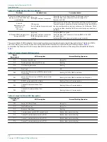
5. Modified CONFIG data is not
being saved.
Loose connection on Main Board
with Non-Volatile Memory.
Turn off power to ACE2 and open enclosure. Check Non-Volatile
memory at U6. (
) Check to make sure it is secure.
6. No IRMS version number is
displayed.
IRMS board not connected via
fiber optic cable
No power.
Connect IRMS board via fiber optic cable to the
ACE2.
Connect power to IRMS board.
7. Every time the ACE2 resets
when using ALCMS Step setting
drops to step 0.
If ACE2 was configured for Stand-
Alone, and
was used in ALCMS mode, upon
reset the ACE2 attempts to go
passive. The Regulator begins to
operate at Step 0.
Call ADB Airfield Solutions, for assistance.
96A0357, Rev. G, 2019/11/08
27
Copyright
©
ADB Safegate, All Rights Reserved
Summary of Contents for ACE2
Page 1: ...Advanced Control Equipment ACE2 User Manual 96A0357 Rev G 2019 11 08 ...
Page 2: ......
Page 18: ...Advanced Control Equipment ACE2 Introduction 12 Copyright ADB Safegate All Rights Reserved ...
Page 42: ...Advanced Control Equipment ACE2 Parts 36 Copyright ADB Safegate All Rights Reserved ...
Page 46: ......


