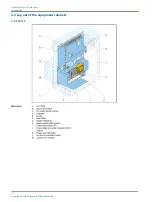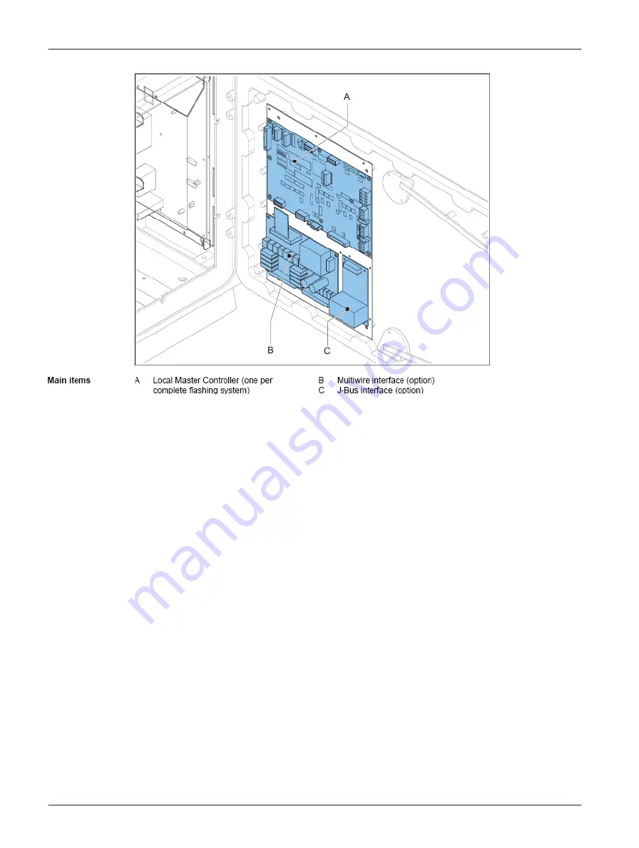
3.2.3 LMC
3.3 Intended use
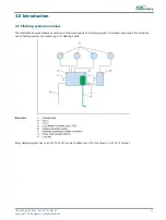
The equipment is designed to control flashes of UEL or FFL type flasher heads.
The flasher heads operate at an approach or a threshold area in sequenced flashing approach lighting systems or RTILS
(REILS) at airports.
The flasher heads flash in a predefined sequence, interval and repetition rate.
Each flash unit that has a fitting needs a separate FCU PCB.
3.4 Description
Introduction
The equipment cabinets in the flashing system exist in two variants:
•
FCU-1: one cabinet with one FCU for a single flash unit; single-phase power supply;
•
FCU-3: one cabinet with three FCUs for 3 flash units: three-phase power supply.
It is possible to combine these two types of cabinets in one system. Then, FCU-1 cabinets must have a separate junction
box (option) to connect to the three-phase power supply.
It is possible to connect the FCU-3 in a single-phase power supply. Then the number of flash units is limited to an RTILS.
Each equipment is an autonomous device and receives an unique sequence number that serves as a logical address.
The maximum number of equipments in a flashing system that is controlled by one LMC is 32.
Flashing System Maintenance
Introduction
14
Copyright
©
ADB Safegate, All Rights Reserved
Summary of Contents for FCU-1-in-1
Page 2: ......
Page 8: ...Flashing System Maintenance TABLE OF CONTENTS viii Copyright ADB Safegate All Rights Reserved ...
Page 18: ...Flashing System Maintenance Safety 8 Copyright ADB Safegate All Rights Reserved ...
Page 28: ...Flashing System Maintenance Introduction 18 Copyright ADB Safegate All Rights Reserved ...
Page 42: ...Flashing System Maintenance Commissioning 32 Copyright ADB Safegate All Rights Reserved ...
Page 64: ...Flashing System Maintenance Maintenance 54 Copyright ADB Safegate All Rights Reserved ...
Page 106: ...Flashing System Maintenance Technical data 96 Copyright ADB Safegate All Rights Reserved ...
Page 110: ......


