The multiwire interface provides control and back-indication signals for basic remote control functions between the
equipment and a remote control system.
The terminals of the multiwire PBC handle the incoming and outgoing signals between the equipment and the remote control
system.
Note
The factory settings apply a specific signal to one terminal. If you want to make changes, this is possible when you
commission with the configuration software tool. It is necessary to configure a specific signal only to one terminal.
Control signals
The control signals feed relay coils. An RC circuit protects the relay coils for transient over- voltage.
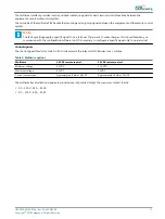
Table 3: Multiwire options
Multiwire
48 VDC remote control
24 VDC remote control
Minimum voltage
40 VDC
21.6 VDC
Maximum voltage
65 VDC
35 VDC
Current consumption
Approximately 9 mA at 48 VDC
Approximately 16 mA at 24 VDC
The multiwire back-indication signals are provided over dry contact relays. The maximum contact load is:
•
AC - 110 V -0.5 A - 60 VA
•
DC - 110 V -0.5 A - 30 W
UM-4019_AM02-620e, Rev. 3.0, 2020/05/12
17
Copyright
©
ADB Safegate, All Rights Reserved
Summary of Contents for FCU-1-in-1
Page 2: ......
Page 8: ...Flashing System Maintenance TABLE OF CONTENTS viii Copyright ADB Safegate All Rights Reserved ...
Page 18: ...Flashing System Maintenance Safety 8 Copyright ADB Safegate All Rights Reserved ...
Page 28: ...Flashing System Maintenance Introduction 18 Copyright ADB Safegate All Rights Reserved ...
Page 42: ...Flashing System Maintenance Commissioning 32 Copyright ADB Safegate All Rights Reserved ...
Page 64: ...Flashing System Maintenance Maintenance 54 Copyright ADB Safegate All Rights Reserved ...
Page 106: ...Flashing System Maintenance Technical data 96 Copyright ADB Safegate All Rights Reserved ...
Page 110: ......


