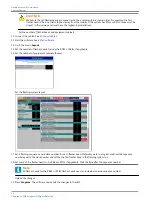
Note
From the moment that the communication is established between the dongle and the equipment, you can not
control the flashing system with local or remote control.
2. Enable software configuration.
3. Set the number of equipments in the system.
4. Restart the LMC.
5. Define the system layout with the configuration software tool.
6. Define the flashing mode with the configuration software tool.
Enable software configuration
7. Set the dip-switch 4 of the dip-switch bank SW4 of the LMC PCB to OFF.
Set number of flasher heads in system
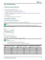
8. Set the dip-switches of the dip-switch bank SW5 of the LMC PCB.
•
Dip-switches 1 to 6: set the same as for SW2 for the last flasher head in the flashing system. See §
.
•
Dip-switch 8: ON. Dip-switch 8 allows the communication over the dongle to the LMC PCB.
Restart LMC
9. Make sure that the all equipment cabinets in the system are switched ON.
10. Switch OFF the unit that has the LMC. Leave the power off for approximately 10 seconds.
11. Switch ON the unit that has the LMC. Use the fused input switch. Now the flashing system activates the dip-switch settings
Define flashing system layout
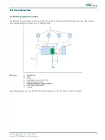
Flashing system layout:
•
Number of flasher heads;
•
Number of equipment cabinets;
•
Flashing rhythm and order
UM-4019_AM02-620e, Rev. 3.0, 2020/05/12
23
Copyright
©
ADB Safegate, All Rights Reserved
Summary of Contents for FCU-1-in-1
Page 2: ......
Page 8: ...Flashing System Maintenance TABLE OF CONTENTS viii Copyright ADB Safegate All Rights Reserved ...
Page 18: ...Flashing System Maintenance Safety 8 Copyright ADB Safegate All Rights Reserved ...
Page 28: ...Flashing System Maintenance Introduction 18 Copyright ADB Safegate All Rights Reserved ...
Page 42: ...Flashing System Maintenance Commissioning 32 Copyright ADB Safegate All Rights Reserved ...
Page 64: ...Flashing System Maintenance Maintenance 54 Copyright ADB Safegate All Rights Reserved ...
Page 106: ...Flashing System Maintenance Technical data 96 Copyright ADB Safegate All Rights Reserved ...
Page 110: ......


