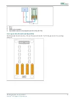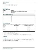
9.0 PCB drawings and settings
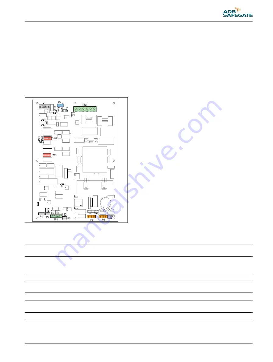
9.1 FCU - PCB1487
The FCU PCB is a CPU-controlled PCB that receives input messages from the LMC or the dongle, via the local bus interface.
The FCU PCB has no direct connection to the remote control system of the user. The PCB contains a SMPS to charge the flash
energy capacitor and has the necessary hardware to drive and monitor the flasher head. It counts the number of misfires and
sends error messages back to the LMC. If the number of flashes exceeds the lifetime of the flasher head, an error is also sent
back.
9.1.1 Layout of the Printed Circuit Board (PCB)
The board has a fuse (A) of 2AT or 2AF, 5 x 20 with 1.5 A breaking capability.
9.1.2 Connectors
Table 31: FCU PCB connectors
Name
Type
Description
Factory
wiring
External
wiring
Notes
P1
5-pin Stocko
To monitor the temperature sensor.
x
Only one temperature sensor per
flashing system that is connected to
the LMC.
P2
3-pin Stocko
To monitor the door contact.
x
P3
3-pin Stocko
To monitor the MOV
modules.
x
P4
10-pin flat cable
To connect a local bus.
x
P5
3-pin Wago
To connect a heater resistance.
x
Only one heater resistance per
equipment cabinet.
P6
3-pin Wago
Mains supply
x
UM-4019_AM02-620e, Rev. 3.0, 2020/05/12
75
Copyright
©
ADB Safegate, All Rights Reserved
Summary of Contents for FCU-1-in-1
Page 2: ......
Page 8: ...Flashing System Maintenance TABLE OF CONTENTS viii Copyright ADB Safegate All Rights Reserved ...
Page 18: ...Flashing System Maintenance Safety 8 Copyright ADB Safegate All Rights Reserved ...
Page 28: ...Flashing System Maintenance Introduction 18 Copyright ADB Safegate All Rights Reserved ...
Page 42: ...Flashing System Maintenance Commissioning 32 Copyright ADB Safegate All Rights Reserved ...
Page 64: ...Flashing System Maintenance Maintenance 54 Copyright ADB Safegate All Rights Reserved ...
Page 106: ...Flashing System Maintenance Technical data 96 Copyright ADB Safegate All Rights Reserved ...
Page 110: ......


![Navig[8]r NAVBIKE-GPS User Manual preview](http://thumbs.mh-extra.com/thumbs/navig-8-r/navbike-gps/navbike-gps_user-manual_3574097-01.webp)


