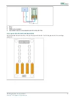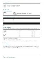
9.3.2 Straps
Table 39: LMC PCB straps
Strap
Bus use
Rx / Tx
Resistor 680 ohms
Terminating resistor 150 ohms
Pull up
Pull down
W1
Remote Bus A
TX-
x
W2
TX+
x
W3
TX
x
W4
Rx+
x
W5
Rx-
x
W6
Rx
x
W7
Remote Bus B
x
W8
TX
x
W9
TX+
x
W10
TX-
x
W11
Rx+
x
W12
Rx
x
W13
Reserved
x
W14
+
x
W15
Local bus
x
W16
+
x
W17
Synchro line
x
W18
Local bus
x
W19
Bus A
Between 1 and 2
Wiring of the bus: 2 wires (RS485)
Between 2 and 3
Wiring of the bus: 4 wires (RS422)
W20
Bus B
Between 1 and 2
Wiring of the bus: 2 wires (RS485)
Between 2 and 3
Wiring of the bus: 4 wires (RS422)
Notes
1
Reserved for future use.
2
Reserved for future use.
3
Reserved for future use.PCB drawings and settings
9.3.3 Rotary and dip-switches
If not specifically noted, all the switches are read only at power-up. If you change a switch setting, restart the equipment
before the changed comes into effect.
UM-4019_AM02-620e, Rev. 3.0, 2020/05/12
81
Copyright
©
ADB Safegate, All Rights Reserved
Summary of Contents for FCU-1-in-1
Page 2: ......
Page 8: ...Flashing System Maintenance TABLE OF CONTENTS viii Copyright ADB Safegate All Rights Reserved ...
Page 18: ...Flashing System Maintenance Safety 8 Copyright ADB Safegate All Rights Reserved ...
Page 28: ...Flashing System Maintenance Introduction 18 Copyright ADB Safegate All Rights Reserved ...
Page 42: ...Flashing System Maintenance Commissioning 32 Copyright ADB Safegate All Rights Reserved ...
Page 64: ...Flashing System Maintenance Maintenance 54 Copyright ADB Safegate All Rights Reserved ...
Page 106: ...Flashing System Maintenance Technical data 96 Copyright ADB Safegate All Rights Reserved ...
Page 110: ......


